SK100EL16V(2001) Ver la hoja de datos (PDF) - Semtech Corporation
Número de pieza
componentes Descripción
Fabricante
SK100EL16V Datasheet PDF : 9 Pages
| |||
SK10/100EL16V
HIGH-PER.ORMANCE PRODUCTS
AC Characteristics
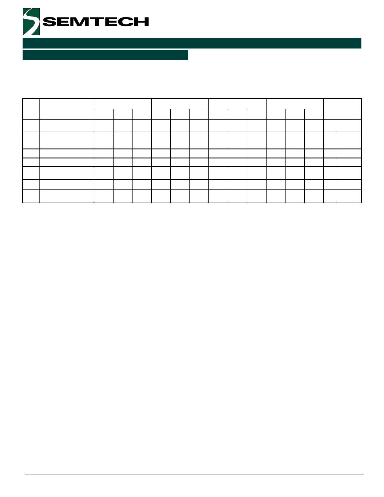
SK10/100EL16V AC Electrical Characteristics
(VCC – VEE = 3.0V to 5.5V; VOUT loaded 50Ω to VCC – 2.0V)
Symbol Characteristic
fmax
tPLH
tPHL
AV
tskew
tr , tf
Maximum Toggle
.requency4
Input to Output Delay
(DI..)
(SE)
Small Signal Gain6
Duty Cycle Skew3
(DI..)
Output Rise/.all Times
Q (20% to 80%)
VCMR
Common Mode Range7
VOP-P
VOP-P
Output Voltage8
Output Voltage8
TA = –40oC
TA = 0oC
TA = +25oC
TA = +85oC
Min Typ Max Min Typ Max Min Typ Max Min Typ Max Unit
2.0
2.0
2.0
2.0
GHz
275 290 310 280 300 320 290 305 325 295 320 340 ps
250 300 340 250 310 350 250 315 360 250 330 370 ps
32
dB
5
20
5
20
5
20
5
20
ps
120 140 175 135 160 185 135 160 190 140 170 200 ps
VEE +
1.7
570
VCC VEE +
0.4 1.7
600
VCC VEE +
0.4 1.7
650
VCC VEE +
0.4 1.7
650
VCC
0.4
V
mV
100
100
100
100
mV
Condition
VCTRL = Open
VCTRL = VCC
Notes:
1. 10EL circuits are designed to meet the DC specifications shown in the table after thermal equilibrium
has been established. The circuit is in a test socket or mounted on a printed circuit board and
transverse airflow greater than 500 lfpm is maintained. Outputs are terminated through a 50Ω
resistor to VCC–2.0V.
2. 100K circuits are designed to meet the DC specification shown in the table where transverse airflow
greater than 500 lfpm is maintained.
3. Duty cycle skew is the difference between TPLH and TPHL propagation delay through a device.
4. Fmax guaranteed for functionality only. See Figure 3 for typical output swing. VOP-P levels are
guaranteed at DC only.
5. VCTRL voltage range should be between VBB to VCC.
6. The device has a DC gain of ~40.
7. CMR range is referenced to the most positive side of the differential input signal. Normal operation is
obtained if the high level falls within the specified range and the peak-to-peak voltage lies between
VPP(min) and 1V. The lower end of the CMR range varies 1:1 with VEE and is equal to VEE + 1.7V.
8. VOP-P is obtained as follows: Voltages of Q and Q* outputs with respect to VCC are measured. The
absolute difference between a high and a low state is equal to VOP-P.
9. Voltages referenced to VCC = 0V.
10. Minimum input swing for which parameters are guaranteed.
11. For standard ECL DC specifications, refer to the ECL Logic Family Standard DC Specifications Data
Sheet.
12. For part ordering description, see HPP Part Ordering Information Data Sheet.
Revision 1/February 12, 2001
5
www.semtech.com
Share Link: 