X76F641WE Ver la hoja de datos (PDF) - Xicor -> Intersil
Número de pieza
componentes Descripción
Fabricante
X76F641WE Datasheet PDF : 17 Pages
| |||
X76F641
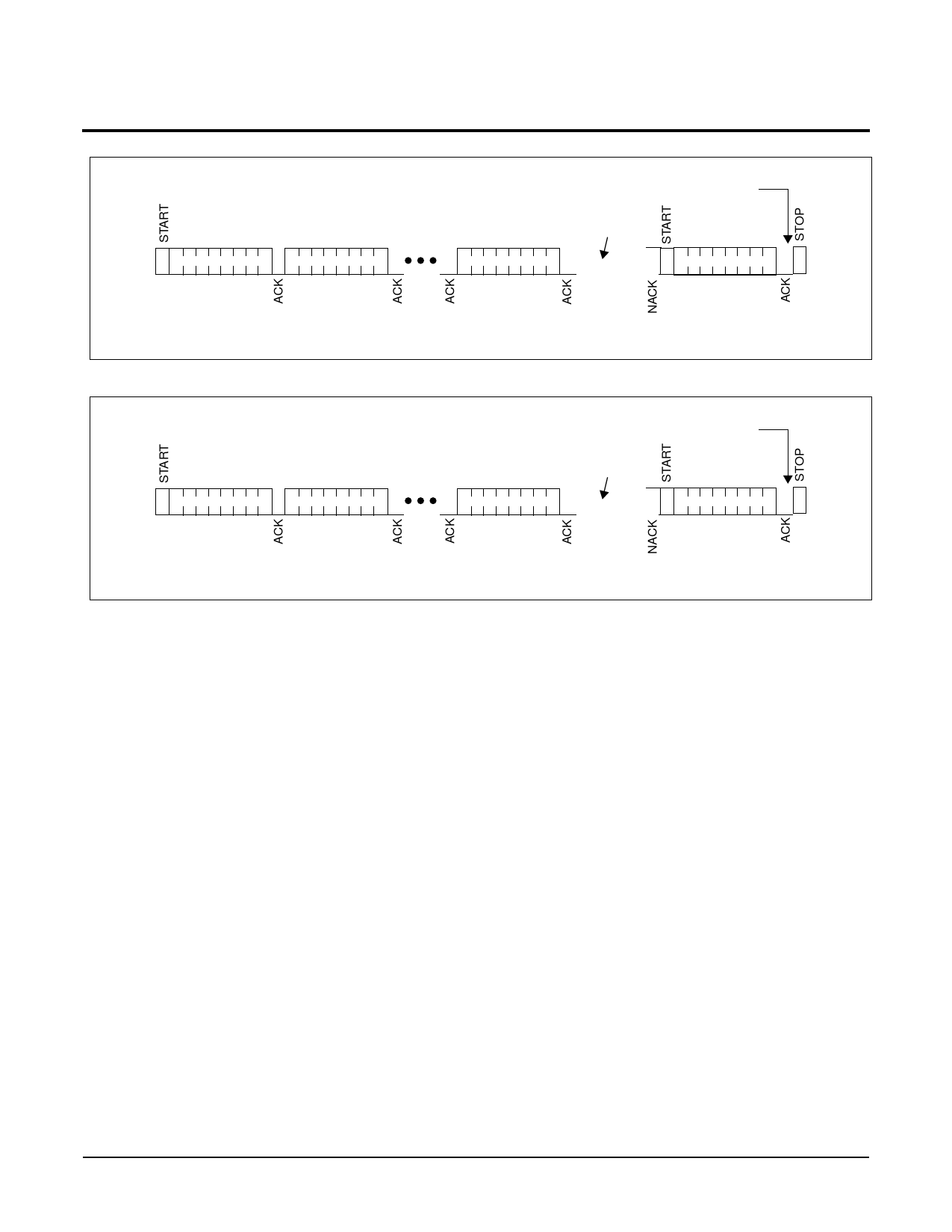
Figure 9. Reset Password
SDA S
Reset Password
COMMAND
Reset
Password
7
Figure 10. Reset Device
SDA S
Reset Device
COMMAND
Reset
Password
7
Reset
Password
0
Wait tWC
OR
Repeated
ACK Polling
Command
If ACK, then
Device reset
ACK POLLING
COMMAND
S
S
7025 FM 14
Reset
Password
0
Wait tWC
OR
Repeated
ACK Polling
Command
If ACK, then
Device reset
ACK POLLING
COMMAND
S
S
7025 FM 15
RESPONSE TO RESET (DEFAULT = 19 41 AA 55)
The ISO Response to reset is controlled by the RST and
CLK pins. When RST is pulsed high during a clock pulse,
the device will output 32 bits of data, one bit per clock,
and it resets to the standby state. This conforms to the
ISO standard for “synchronous response to reset”. The
part must not be in a write cycle for the response to reset
to occur.
After initiating a nonvolatile write cycle the RST pin must
not be pulsed until the nonvolatile write cycle is complete.
If not, the ISO response will not be activated. If the RST
is pulsed HIGH and the CLK is within the RST pulse
(meet the tNOL spec.) in the middle of an ISO transaction,
it will output the 32 bit sequence again (starting at bit 0).
Otherwise, this aborts the ISO operation and the part
returns to standby state. If the RST is pulsed HIGH and
the CLK is outside the RST pulse (in the middle of an
ISO transaction), this aborts the ISO operation and the
part returns to standby state.
If there is power interrupted during the Response to
Reset, the response to reset will be aborted and the part
will return to the standby state. A Response to Reset is
not available during a nonvolatile write cycle.
9
Share Link: 