VDP313XY Ver la hoja de datos (PDF) - Micronas
Número de pieza
componentes Descripción
Fabricante
VDP313XY Datasheet PDF : 76 Pages
| |||
VDP 313xY
ADVANCE INFORMATION
2.3. Adaptive Comb Filter
The adaptive comb filter is used for high-quality lumi-
nance/chrominance separation for PAL or NTSC sig-
nals. The comb filter improves the luminance resolu-
tion (bandwidth) and reduces interferences like
cross-luminance and cross-color artifacts. The adap-
tive algorithm can eliminate most of the mentioned
errors without introducing new artifacts or noise.
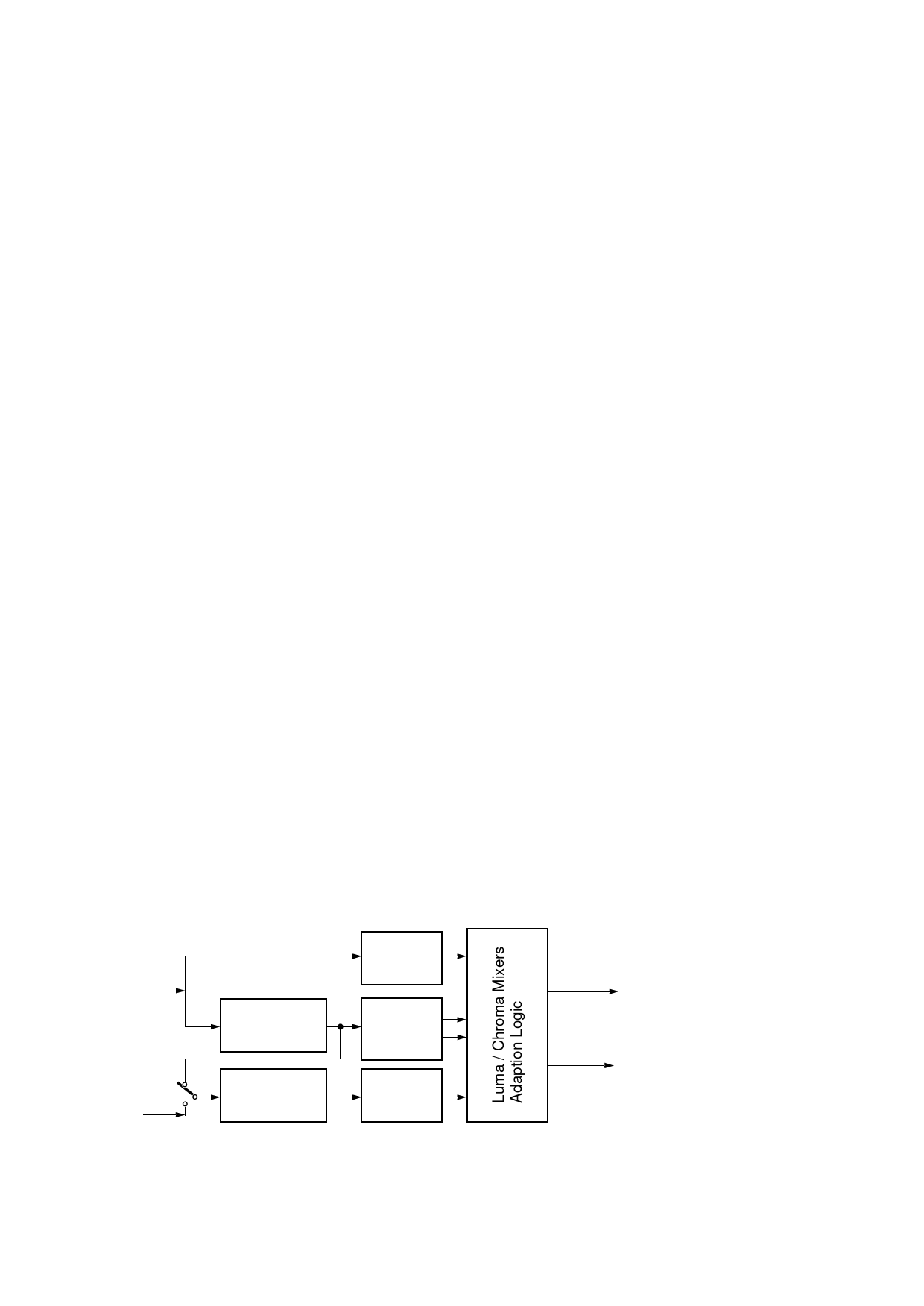
A block diagram of the comb filter is shown in Fig. 2–1.
The filter uses two line delays to process the informa-
tion of three adjacent video lines. To have a fixed
phase relationship of the color subcarrier in the three
channels, the system clock (20.25 MHz) is fractionally
locked to the color subcarrier. This allows the process-
ing of all color standards and substandards using a
single crystal frequency.
The CVBS signal in the three channels is filtered at the
subcarrier frequency by a set of bandpass/notch fil-
ters. The output of the three channels is used by the
adaption logic to select the weighting that is used to
reconstruct the luminance/chrominance signal from
the 4 bandpass/notch filter signals. By using soft mix-
ing of the 4 signals switching artifacts of the adaption
algorithm are completely suppressed.
The comb filter uses the middle line as reference,
therefore, the comb filter delay is one line. If the comb
filter is switched off, the delay lines are used to pass
the luminance/ chrominance signals from the A/D con-
verters to the luminance/ chrominance outputs. Thus,
the comb filter delay is always one line.
Various parameters of the comb filter are adjustable,
hence giving to the user the ability to adjust his own
desired picture quality.
Two parameters (KY, KC) set the global gain of lumi-
nance and chrominance comb separately; these val-
ues directly weigh the adaption algorithm output. In
this way, it is possible to obtain a luminance/chromi-
nance separation ranging from standard notch/band-
pass to full comb decoding.
The parameter KB allows to choose between the two
proposed comb booster modes. This so-called feature
widely improves vertical high to low frequency transi-
tions areas, the typical example being a multiburst to
dc change. For KB = 0, this improvement is kept mod-
erate, whereas, in case of KB = 1, it is maximum, but
the risk to increase the “hanging dots” amount for
some given color transitions is higher.
Using the default setting, the comb filter has separate
luminance and chrominance decision algorithms; it is
however possible to switch the chrominance comb fac-
tor to the current luminance adaption output by setting
CC to 1.
Another interesting feature is the programmable limita-
tion of the luminance comb amount; proper limitation,
associated to adequate luminance peaking, gives rise
to an enhanced 2-D resolution homogeneity. This limi-
tation is set by the parameter CLIM, ranging from 0 (no
limitation) to 31 (max. limitation).
The DAA parameter (1:off, 0:on) is used to disable/
enable a very efficient built-in “rain effect” suppressor;
many comb filters show this side effect which gives
some vertical correlation to a 2-D uniform random
area, due to the vertical filtering. This unnatural-look-
ing phenomenon is mostly visible on tuner images,
since they are always corrupted by some noise; and
this looks like rain.
CVBS Input
Chroma Input
1H Delay Line
1H Delay Line
Bandpass
Filter
Bandpass/
Notch
Filter
Bandpass
Filter
Fig. 2–1: Block diagram of the adaptive comb filter (PAL mode)
8
Luma Output
Chroma Output
Micronas
Share Link: 