TZA3041 Ver la hoja de datos (PDF) - Philips Electronics
Número de pieza
componentes Descripción
Fabricante
TZA3041 Datasheet PDF : 32 Pages
| |||
Philips Semiconductors
Gigabit Ethernet/Fibre Channel laser
drivers
Product specification
TZA3041AHL; TZA3041BHL;
TZA3041U
handbook, halfpaTgZe ERO, TONE
<1 nA
<1 nA
40 pF
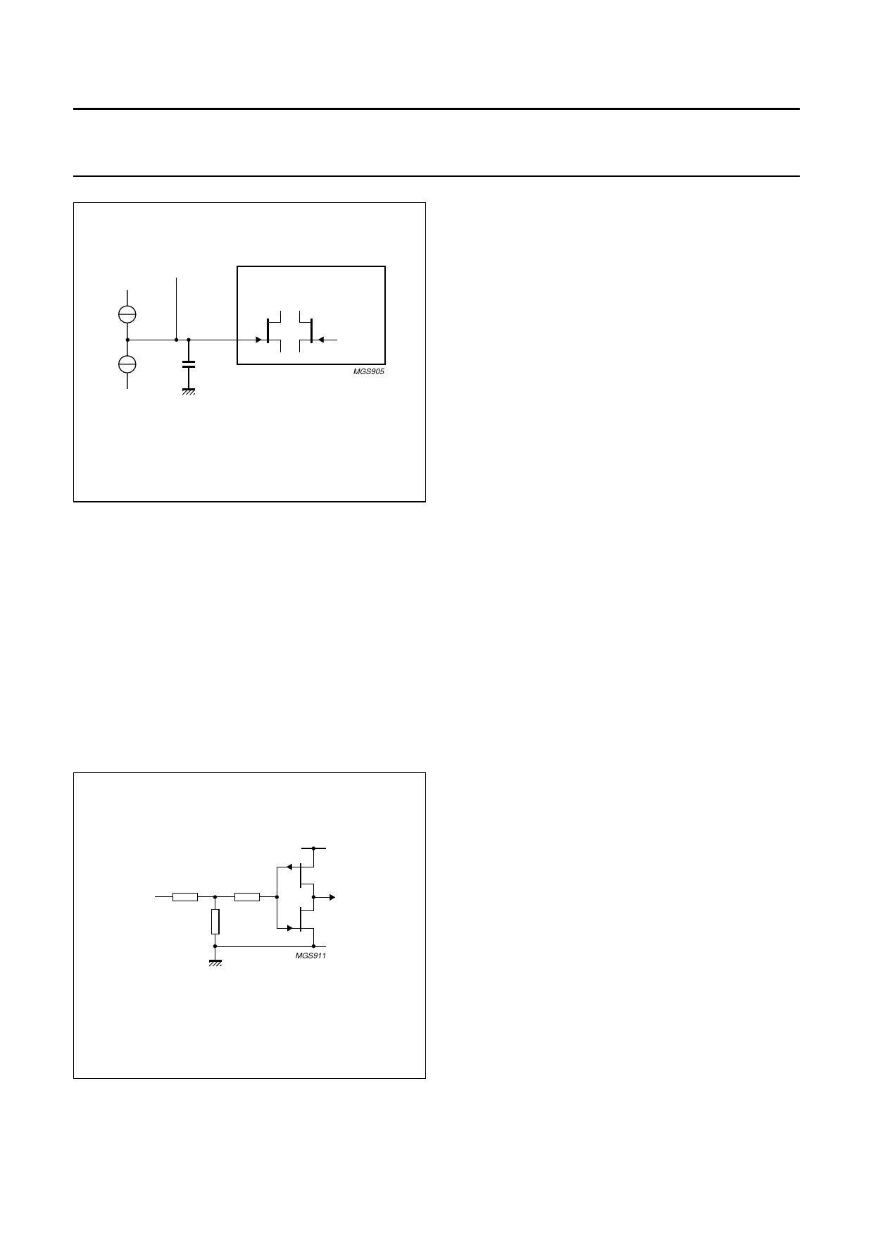
LINEAR VOLTAGE TO
CURRENT CONVERTER
2.4 V
MGS905
GND
Fig.10 TZERO and TONE internal configuration.
Automatic laser shut-down and laser slow start
The laser modulation and bias currents can be rapidly
switched off when a HIGH level (CMOS) is applied to
pin ALS. This function allows the circuit to be shut-down in
the event of an optical system malfunction. A 25 kΩ
pull-down resistor defaults pin ALS to the non active state
(see Fig.11).
When a LOW level is applied to pin ALS, the modulation
and bias currents slowly increase to the desired values at
the typical time constants of τONE and τZERO, respectively.
This can be used to slow-start the laser.
Manual laser override
The automatic laser control function can be overridden by
connecting voltage sources to pins TZERO and TONE to
take direct control of the current sources for bias and
modulation respectively. The control voltages should
range from 1.4 to 3.4 V to swing the modulation current
over the range 1 to 60 mA and the bias current over the
range 1 to 90 mA. These current ranges are guaranteed.
Due to the tolerance range in the manufacturing process,
some devices may have higher current values than those
specified, as shown in Figs 12 and 13. Both figures show
that temperature changes cause a slight tilting of the linear
characteristic around an input voltage of 2.4 V.
Consequently, the manually controlled current level is
most insensitive to temperature variations at around this
value. Bias and modulation currents in excess of the
specified range are not supported and should be avoided.
Currents into or out of pins TZERO and TONE in excess of
10 µA must be avoided to prevent damage to the circuit.
handbook, halfpage
100 Ω
ALS
100 Ω
25 kΩ
GND
VCC(R)
MGS911
Fig.11 ALS input.
2002 Aug 13
10
Share Link: 