PC417T Ver la hoja de datos (PDF) - Sharp Electronics
Número de pieza
componentes Descripción
Fabricante
PC417T Datasheet PDF : 5 Pages
| |||
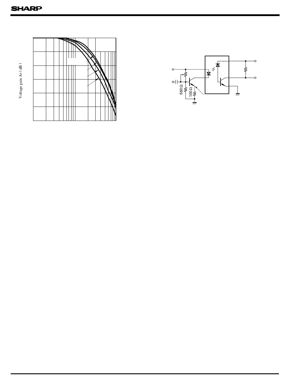
Fig. 9 Frequency Response
0
-5
RL = 100 Ω
- 10
220 Ω
470 Ω
- 15
1k Ω
- 20
IF = 16mA
Ta = 25˚C
- 25
- 30
0.1 0.2
0.5 1
2
Frequency f ( MHz )
5 10
PC417
Test Circuit for Frequency Response
5V
AC
Input
20k Ω
15V
RL
VO
1.6V DC
0.25VP - PAC
s Precautions for Use
( 1) It is recommended that a by-pass capacitor of more than 0.01µF be added between VCC and
GND near the device in order to stabilize power supply line.
( 2) Transistor of detector side in bipolar configuration is apt to be affected by static electricity
for its minute design. When handling them, general counterplan against static electricity
should be taken to avoid breakdown of devices or degradation of characteristics.
( 3) As for other general cautions, refer to the chapter “ Precautions for Use ”
Share Link: 