TS27L4IPT(2009) Ver la hoja de datos (PDF) - STMicroelectronics
Número de pieza
componentes Descripción
Fabricante
TS27L4IPT Datasheet PDF : 15 Pages
| |||
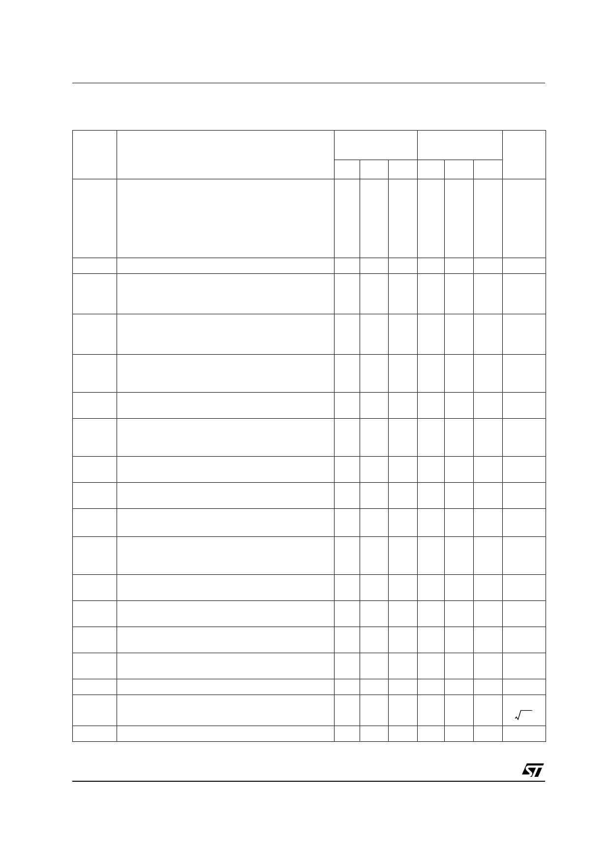
Absolute maximum ratings and operating conditions
TS27L4
2
Absolute maximum ratings and operating conditions
Table 1. Absolute maximum ratings
Symbol
VCC+
Vid
Vin
Io
Iin
Tstg
Rthja
Rthjc
ESD
Parameter
Supply voltage (1)
Differential input voltage (2)
Input voltage (3)
Output current for VCC+ ≥ 15V
Input current
Storage temperature range
Thermal resistance junction to ambient(4)
SO-14
TSSOP14
DIP14
Thermal resistance junction to case(4)
SO-14
TSSOP14
DIP14
HBM: human body model(5)
MM: machine model(6)
CDM: charged device model(7)
Value
18
±18
-0.3 to 18
±30
±5
-65 to +150
105
100
80
31
32
33
1
100
1.5
Unit
V
V
V
mA
mA
°C
°C/W
°C/W
kV
V
kV
1. All values, except differential voltage are with respect to network ground terminal.
2. Differential voltages are the non-inverting input terminal with respect to the inverting input terminal.
3. The magnitude of the input and the output voltages must never exceed the magnitude of the positive
supply voltage.
4. Short-circuits can cause excessive heating and destructive dissipation. Values are typical.
5. Human body model: a 100 pF capacitor is charged to the specified voltage, then discharged through a
1.5 kΩ resistor between two pins of the device. This is done for all couples of connected pin combinations
while the other pins are floating.
6. Machine model: a 200 pF capacitor is charged to the specified voltage, then discharged directly between
two pins of the device with no external series resistor (internal resistor < 5 Ω). This is done for all couples of
connected pin combinations while the other pins are floating.
7. Charged device model: all pins and the package are charged together to the specified voltage and then
discharged directly to the ground through only one pin. This is done for all pins.
Table 2. Operating conditions
Symbol
Parameter
TS27L4C
TS27L4I
Unit
VCC+ Supply voltage
3 to 16
V
Vicm Common mode input voltage range
0 to VCC+ - 1.5
V
Toper Operating free-air temperature range
0 to +70
-40 to +125
°C
4/15
Share Link: 