MX7576J Ver la hoja de datos (PDF) - Maxim Integrated
NГғmero de pieza
componentes DescripciГіn
Fabricante
MX7576J Datasheet PDF : 12 Pages
| |||
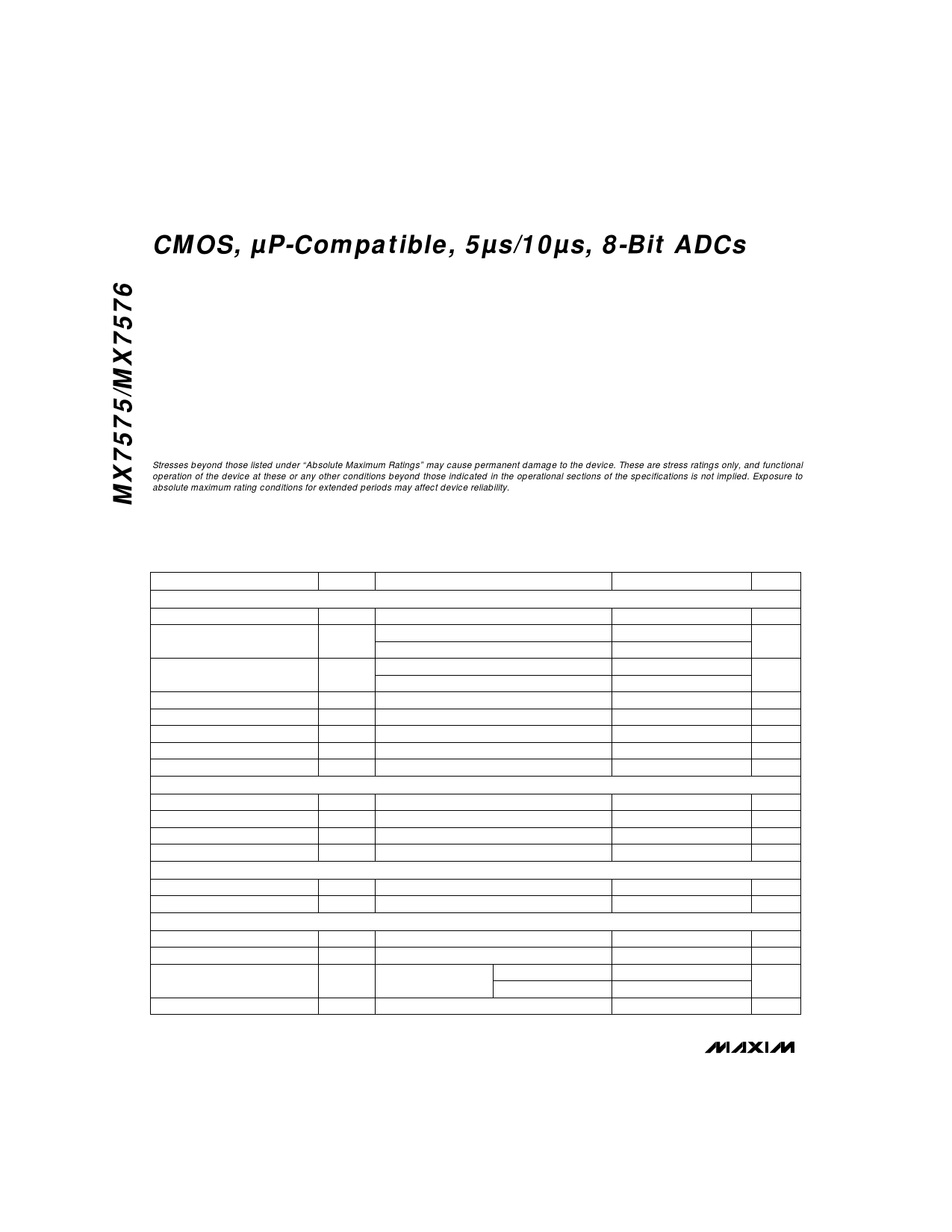
CMOS, ВµP-Compatible, 5Вµs/10Вµs, 8-Bit ADCs
ABSOLUTE MAXIMUM RATINGS
VDD to AGND...............................................................-0.3V, +7V
VDD to DGND ..............................................................-0.3V, +7V
AGND to DGND ...............................................-0.3V, VDD + 0.3V
Digital Input Voltage to DGND
(CS, RD, TP, MODE) ......................................-0.3V, VDD + 0.3V
Digital Output Voltage to DGND
(BUSY, D0–D7) ..............................................-0.3V, VDD + 0.3V
CLK Input Voltage to DGND ............................-0.3V, VDD + 0.3V
REF to AGND ...................................................-0.3V, VDD + 0.3V
AIN to AGND....................................................-0.3V, VDD + 0.3V
Continuous Power Dissipation (TA = +70В°C)
Plastic DIP (derate 11.11mW/В°C above +70В°C) ...............889mW
Wide SO (derate 9.52mW/В°C above +70В°C)..................762mW
CERDIP (derate 10.53mW/В°C above +70В°C) .................842mW
PLCC (derate 10.00mW/В°C above +70В°C) ....................800mW
Operating Temperature Ranges
MX757_J/K ............................................................0В°C to +70В°C
MX757_A/B ........................................................-25В°C to +85В°C
MX757_JE/KE ....................................................-40В°C to +85В°C
MX757_S/T.......................................................-55В°C to +125В°C
Storage Temperature Range .............................-65В°C to +160В°C
Lead Temperature (soldering,10sec) ..............................+300В°C
Stresses beyond those listed under “Absolute Maximum RatingsвЂқ may cause permanent damage to the device. These are stress ratings only, and functional
operation of the device at these or any other conditions beyond those indicated in the operational sections of the specifications is not implied. Exposure to
absolute maximum rating conditions for extended periods may affect device reliability.
ELECTRICAL CHARACTERISTICS
(VDD = +5V; VREF = 1.23V; AGND = DGND = 0V; fCLK = 4MHz external for MX7575; fCLK = 2MHz external for MX7576;
TA = TMIN to TMAX, unless otherwise noted.)
PARAMETER
SYMBOL
CONDITIONS
MIN TYP MAX UNITS
ACCURACY
Resolution
8
Bits
Total Unadjusted Error
MX757_K/B/T
TUE
MX757_J/A/S
В±1
LSB
В±2
Relative Accuracy
MX757_K/B/T
INL
MX757_J/A/S
В±1/2
LSB
В±1
No-Missing-Codes Resolution
8
Bits
Full-Scale Error
В±1
LSB
Full-Scale Tempco
В±5
ppm/В°C
Offset Error (Note 1)
В±1/2 LSB
Offset Tempco
В±5
ppm/В°C
ANALOG INPUT
Voltage Range
DC Input Impedance
1LSB = 2VREF/256
0
2VREF
V
10
MΩ
Slew Rate, Tracking
MX7575
0.386 V/Вµs
Signal-to-Noise Ratio (Note 2)
SNR MX7575, VIN = 2.46Vp-p at 10kHz, Figure 13
45
dB
REFERENCE INPUT
Reference Voltage
Reference Current
LOGIC INPUTS CS, RD, MODE
VREF
IREF
В±5% variation for specified performance
1.23
V
500
ВµA
Input Low Voltage
Input High Voltage
Input Current
Input Capacitance (Note 2)
VINL
VINH
2.4
IIN
VIN = 0V or VDD
TA = +25В°C
TA = TMIN to TMAX
CIN
0.8
V
V
В±1
ВµA
В±10
10
pF
2 _______________________________________________________________________________________
Share Link: 