TNY274PG Ver la hoja de datos (PDF) - Power Integrations, Inc
Número de pieza
componentes Descripción
Fabricante
TNY274PG Datasheet PDF : 24 Pages
| |||
load is proportional to the primary inductance of the transformer
and peak primary current squared. Hence, designing the supply
involves calculating the primary inductance of the transformer
for the maximum output power required. If the TinySwitch-III
is appropriately chosen for the power level, the current in the
calculated inductance will ramp up to current limit before the
DCMAX limit is reached.
Enable Function
TinySwitch-III senses the EN/UV pin to determine whether or
VEN
CLOCK
DCMAX
IDRAIN
VDRAIN
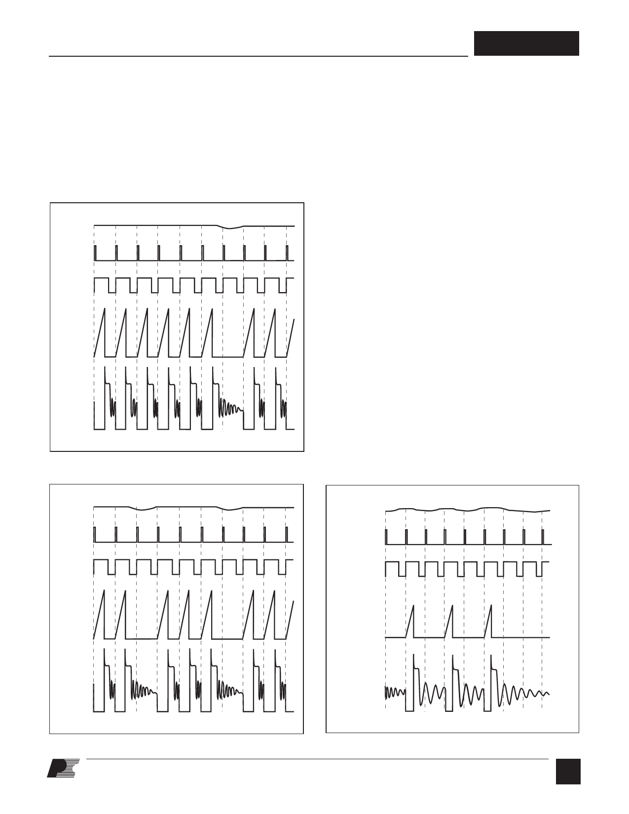
Figure 6. Operation at Near Maximum Loading.
PI-2749-082305
TNY274-280
not to proceed with the next switching cycle. The sequence of
cycles is used to determine the current limit. Once a cycle is
started, it always completes the cycle (even when the EN/UV
pin changes state half way through the cycle). This operation
results in a power supply in which the output voltage ripple
is determined by the output capacitor, amount of energy per
switch cycle and the delay of the feedback.
The EN/UV pin signal is generated on the secondary by
comparing the power supply output voltage with a reference
voltage. The EN/UV pin signal is high when the power supply
output voltage is less than the reference voltage.
In a typical implementation, the EN/UV pin is driven by an
optocoupler. The collector of the optocoupler transistor is
connected to the EN/UV pin and the emitter is connected to
the SOURCE pin. The optocoupler LED is connected in series
with a Zener diode across the DC output voltage to be regulated.
When the output voltage exceeds the target regulation voltage
level (optocoupler LED voltage drop plus Zener voltage), the
optocoupler LED will start to conduct, pulling the EN/UV pin
low. The Zener diode can be replaced by a TL431 reference
circuit for improved accuracy.
ON/OFF Operation with Current Limit State Machine
The internal clock of the TinySwitch-III runs all the time. At
the beginning of each clock cycle, it samples the EN/UV pin to
decide whether or not to implement a switch cycle, and based
on the sequence of samples over multiple cycles, it determines
the appropriate current limit. At high loads, the state machine
sets the current limit to its highest value. At lighter loads, the
state machine sets the current limit to reduced values.
VEN
CLOCK
DCMAX
VEN
CLOCK
DCMAX
IDRAIN
IDRAIN
VDRAIN
VDRAIN
PI-2667-082305
Figure 7. Operation at Moderately Heavy Loading.
Figure 8. Operation at Medium Loading.
PI-2377-082305
E
2/06
5
Share Link: 