TLP2105(2008) Ver la hoja de datos (PDF) - Toshiba
Número de pieza
componentes Descripción
Fabricante
TLP2105 Datasheet PDF : 11 Pages
| |||
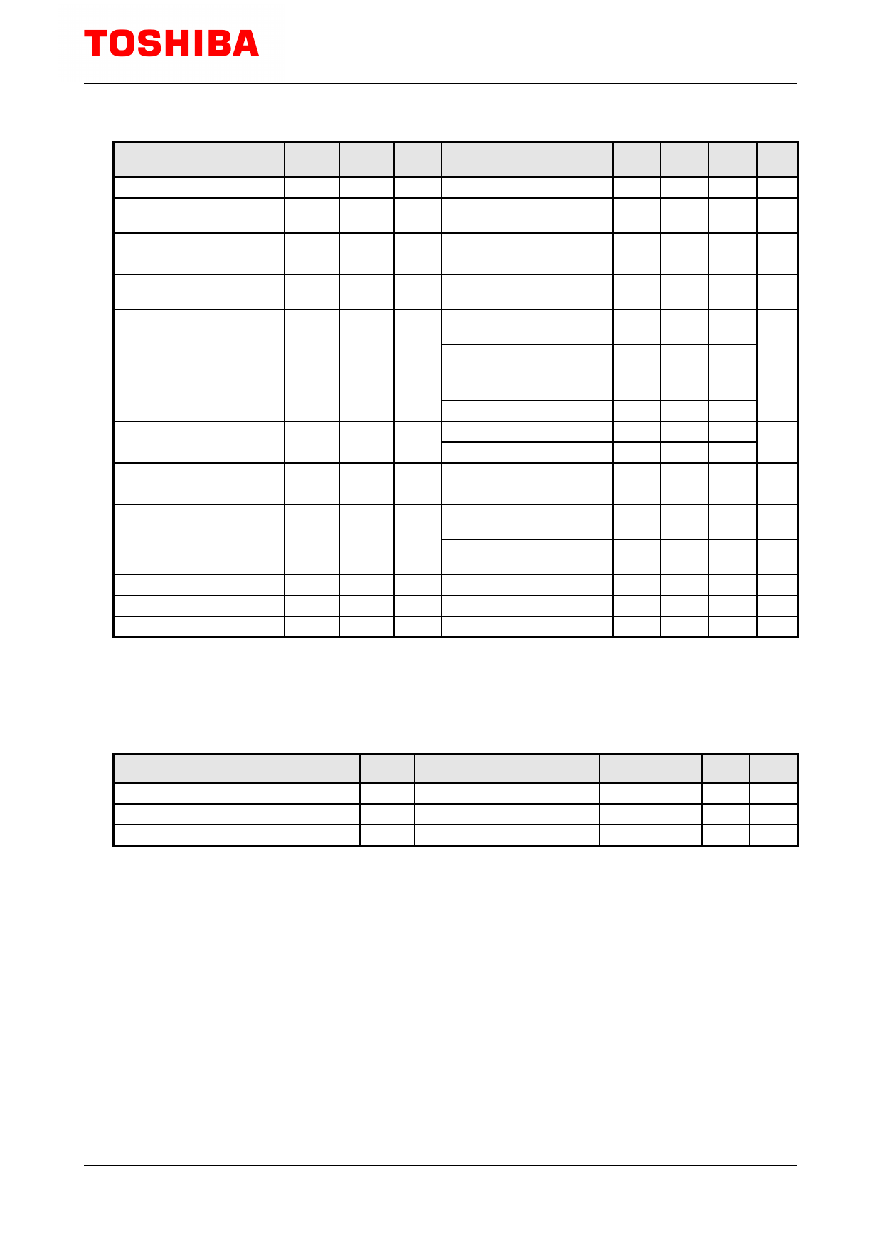
TLP2105
Switching Characteristics
(Unless otherwise specified, Ta=-40 to 100℃、VCC=4.5 to 20 V)(Each Channel)
CHARACTERISTIC
TEST
SYMBOL CIRCUIT
TEST CONDITION
MIN TYP. MAX UNIT
Propagation Delay Time
to Logic High output
tpLH
IF=0→3 mA
30
150
250
ns
Propagation Delay Time
to Logic Low output
Switching Time Dispersion
between ON and OFF
Rise Time (10 – 90 %)
Fall Time (90 – 10 %)
Common Mode transient
Immunity at High Level Output
Common Mode transient
Immunity at Low Level Output
tpHL
|tpHL-
tpLH|
tr
tf
CMH
CML
IF=3→0 mA
7,8
―
30
150
250
ns
―
―
220
ns
IF=0→3 mA , VCC=5 V
―
30
IF=3→0 mA , VCC=5 V
―
30
VCM=1000 Vp-p, IF=5 mA,
VCC=20 V, Ta=25°C
-10000
―
9
VCM=1000 Vp-p, IF=0 mA,
VCC=20 V, Ta=25°C
10000
―
75
ns
75
ns
―
V/μs
―
V/μs
*All typical values are at Ta=25°C
Note 5: A ceramic capacitor (0.1 μA) should be connected from pin 8 to pin 5 to stabilize the operation of the high gain
linear amplifier. Failure to provide the bypassing may impair the switching property. The total lead length between
capacitor and coupler should not exceed 1 cm.
TEST CIRCUIT 1: VOL Test Circuit
TEST CIRCUIT 2: VOH Test Circuit
VF
1
2
3
4
8
VCC
7
6
GND 5
IO VOL VCC
V
0.1 μF
IF 1
2
3
4
8
VCC 7
6
GND 5
IO VO
V
0.1 μF
VCC
SHIELD
SHIELD
TEST CIRCUIT 3: ICCL Test Circuit
1
8
ICCL
VCC
A
2
7
3
6 0.1 μF
VCC
4
GND 5
SHIELD
TEST CIRCUIT 4: ICCH Test Circuit
IF1 1
8
VCC
ICCH
A
2
7
3
4
IF2
6
GND 5
SHIELD
0.1 μF
VCC
TEST CIRCUIT 5: IOSL Test Circuit
1
8
VCC
2
7 IOSL
A
3
6
4
GND 5 0.1 μF VO
SHIELD
TEST CIRCUIT 6: IOSH Test Circuit
IF 1
8
VCC
2
7
VCC
3
6
IOSH VO
VCC
A
4
GND 5 0.1 μF
SHIELD
4
2008-11-26
Share Link: 