TEA2029 Ver la hoja de datos (PDF) - STMicroelectronics
Número de pieza
componentes Descripción
Fabricante
TEA2029 Datasheet PDF : 47 Pages
| |||
TEA2028 - TEA2029 APPLICATION NOTE
This amplitude changing modifies the open-loop
system gain and therefore the damping coefficient
and the locking time constant.
The device will be in short time constant mode
under the following two conditions :
- VCR Mode or SCART Connector Mode :
This mode is enabled by a low state on Pin 23.
V23 < 2.1V.
- Transmitter search and tunning.
In order to accelerate the capture, a ”Video Iden-
tification” stage will detect the presence or the
absence of a video signal on input Pin 27, and
deliver accordingly a signal called ”Mute”.
V.3.5 - Video identification stage
This stage will detect the coincidence between the
line sync pulse (if present) and a 2µs pulse issued
from the logic block. This 2µs pulse at line fre-
quency is positionned at the center of line sync
pulse when the first loop ”ϕ1” is locked.
This sampled detection is stored by an external
capacitor connected to Pin 25. The video recogni-
tion status is also available on Pin 24 so as to
enable Sound Muting during station search proc-
ess and the inhibition of Automatic Frequency Tun-
ing.
V.3.5.1 - Block diagram
Figure 28
+
ϕ1
LS
&
2µs
LS
&
IC
750µA
ID
i C(25)
500µA 25
Comparator
Pin
24
C25
4.7nF
4.6V
Frame
Logic
The video recognition signal is delivered by a hys-
teresis comparator.
The recognition time ”TR” is adjustable by an exter-
nal capacitor, as soon as ϕ1 is locked :
-
IC25(AV) =
IC
⋅
2µs
64µs
and :
-
TR
=
C25
⋅
VH
IC25(AV)
=
1.96
⋅
105
⋅
C25
with C25 = 4.7nF ⇒ TR = 1ms
(which is clearly quite fast)
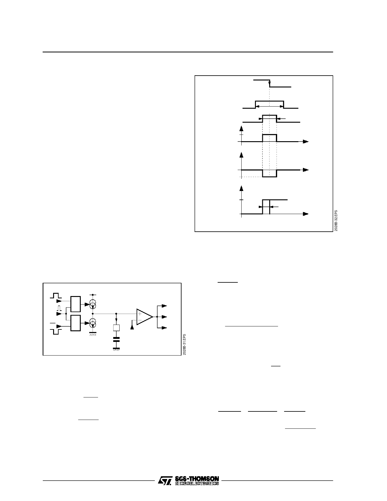
Figure 29
ϕ1
Line Sync.
LS
2µs
IC(25)
IC
4.7µs
2µs
with Video
IC(25)
without Video
ID
Mute
Output
1
0
VHYST = 0.3V
VL VH
V25
4.6V
V.3.6 - Characteristics of loop φ1
V.3.6.1 - Locking accuracy
Let’s study the phase error ”ϕOUT - ϕIN” under
steady state conditions :
The open-loop gain is :
-
T(p)
=
AB f(p)
f
Where :
A = 0.16mA/rd (long time constant)
A = 0.47mA/rd (short time constant)
B = 0.7kHz/V or B = 4.4 103rd/s
-
f(p)
=
R
⋅
(1
+
1 + τ1 p
τ2 p) (1 +
τ3
p)
Where : R = Dynamic input resistance of VCO.
If a phase step of ∆ϕ is applied to the input, the
following would be obtained as a function of (p) :
ΦIN(p)
=
∆Φ
p
Using the last value theorem : lim f(t) = lim p . f(p)
Let’s calculate lim (ϕIN − ϕOUT)
p→0
- The closed-loop gain is :
-
H(p)
=
1
T(p)
+ T(p)
=
p
ABf(p)
+ ABf(p)
=
ΦOUT(p)
ΦIN(p)
that is
: lim p (ΦIN −
p→0
ΦOUT)
= lim
p−>0
p∆Φ
p + AB f(0)
→0
15/46
Share Link: 