TEA6323 Ver la hoja de datos (PDF) - Philips Electronics
Número de pieza
componentes Descripción
Fabricante
TEA6323 Datasheet PDF : 36 Pages
| |||
Philips Semiconductors
Sound fader control circuit
Preliminary specification
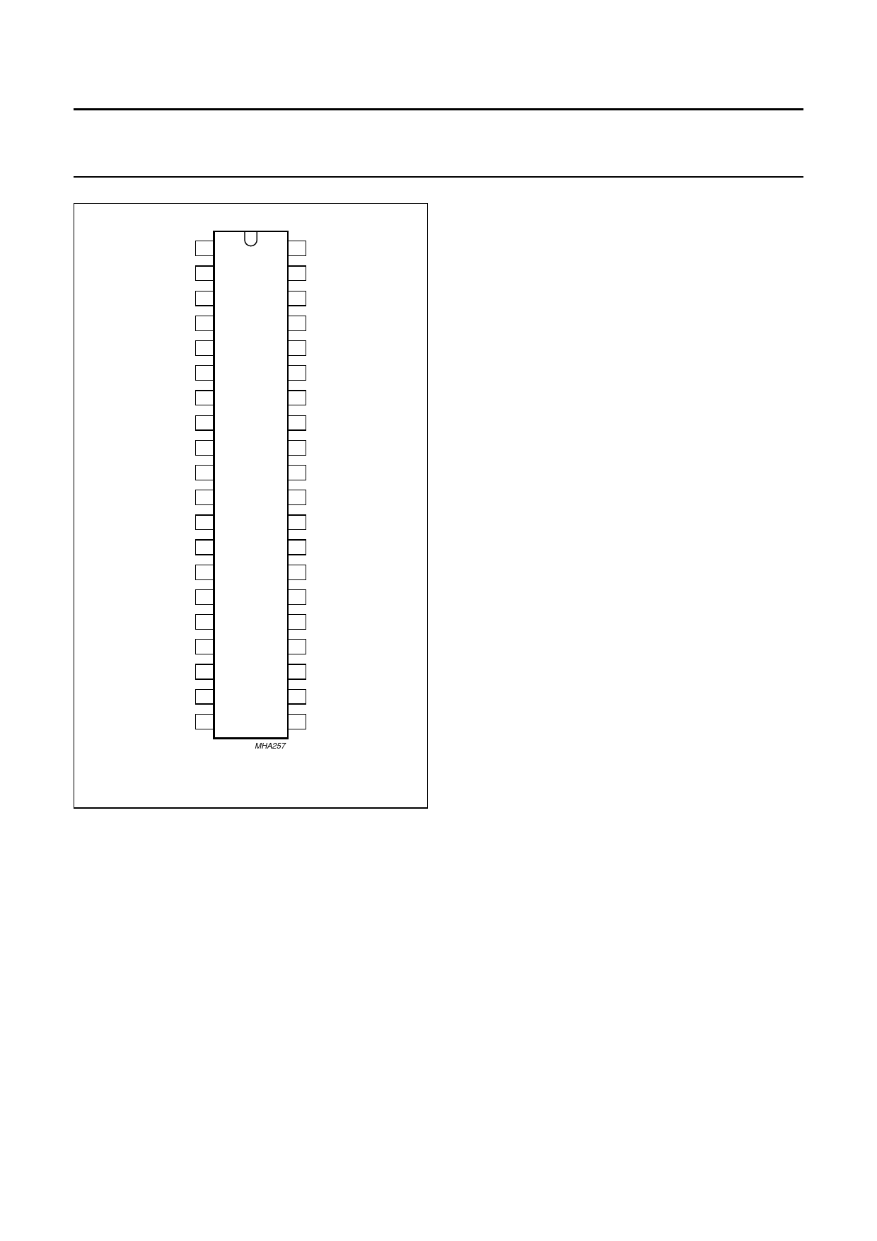
TEA6323T
handbook, halfpage
SDA 1
40 SCL
MUTE 2
DGND 3
AGND 4
39 n.c.
38 VCC
37 n.c.
OUTLR 5
36 OUTRR
OUTLF 6
35 OUTRF
TL 7
34 TR
B2L 8
33 B2R
B1L 9
32 B1R
OVL 10
31 OVR
TEA6323T
IVL 11
30 IVR
ILL 12
29 ILR
QSL 13
28 QSR
IDL 14
i.c. 15
ICL 16
27 IDR
26 Vref
25 ICR
COM 17
24 CAP
IBL 18
23 IBR
i.c. 19
22 i.c.
IAL 20
21 IAR
MHA257
Fig.2 Pin configuration.
FUNCTIONAL DESCRIPTION
The source selector allows either the source selection
between the differential stereo input (IAL, IAR and COM)
and three stereo inputs, or selection of four stereo inputs
and the mono input (COM). The maximum input signal
voltage is Vi(rms) = 2 V. The outputs of the source selector
and the inputs of the following volume control parts are
available at pins 13 and 11 for the left channel and pins 28
and 30 for the right channel. This offers the possibility of
interfacing a noise reduction system.
The volume control part is following the source selector.
The signal phase from input volume control part to all
outputs is 180°.
The volume control function is split into two sections:
volume I control block and volume II control block.
The control range of volume I is between +20 dB and
−31 dB in steps of 1 dB. The volume II control range is
between 0 dB and −55 dB in steps of 1 dB. Although the
theoretical possible control range is 106 dB
(+20 to −86 dB), in practice a range of 86 dB
(+20 to −66 dB) is recommended. The gain/attenuation
setting of the volume I control block is common for both
channels.
The volume I control block operates in combination with
the loudness control. The filter is linear when the maximum
gain for the volume I control (+20 dB) is selected. The filter
characteristic increases automatically over a range of
32 dB down to a setting of −12 dB. That means the
maximum filter characteristic is obtained at −12 dB setting
of volume I. Further reduction of the volume does not
further influence the filter characteristic (see Fig.5). The
maximum selected filter characteristic is determined by
external components. The proposed application gives a
maximum boost of 17 dB for bass and 4.5 dB for treble.
The loudness may be switched on or off via I2C-bus control
(see Table 7).
The volume I control block has an output pin and is
followed by the bass control block. An external filter for
each channel in combination with internal resistors,
provides the frequency response of the bass control (see
Fig.3). The adjustable range is between −18 and +18 dB in
steps of 1.8 dB at 46 Hz.
Both, loudness and bass control result in a maximum bass
boost of 35 dB for low volume settings.
The treble control block offers a control range between
−12 and +12 dB in steps of 1.5 dB at 15 kHz. The filter
characteristic is determined by a single capacitor of 5.6 nF
for each channel in combination with internal resistors
(see Fig.4).
The basic step width of treble control is 3 dB. The
intermediate steps are obtained by switching 1.5 dB boost
and 1.5 dB attenuation steps.
The bass and treble control functions can be switched off
via I2C-bus. In this event the internal signal flow is
disconnected. The connections B2L and B2R are outputs
and TL and TR are inputs for inserting an external
equalizer.
1995 Dec 20
5
Share Link: 