TEA1541 Ver la hoja de datos (PDF) - Philips Electronics
Número de pieza
componentes Descripción
Fabricante
TEA1541 Datasheet PDF : 19 Pages
| |||
Philips Semiconductors
SMPS control IC with
synchronization function
Product specification
TEA1541
handbfook, halfpage
(kHz)
50
25
synchronized operation
6
VCO
variable
unsynchronized operation
VCO
fixed
P(W)
MDB085
Fig.4 Multi mode operation.
handbook, halfpage
M-level
VIN
VCC(start)
VCC(trip)(VIN)
VCC
IVIN(max)
IVIN(min)
IVIN
ICC
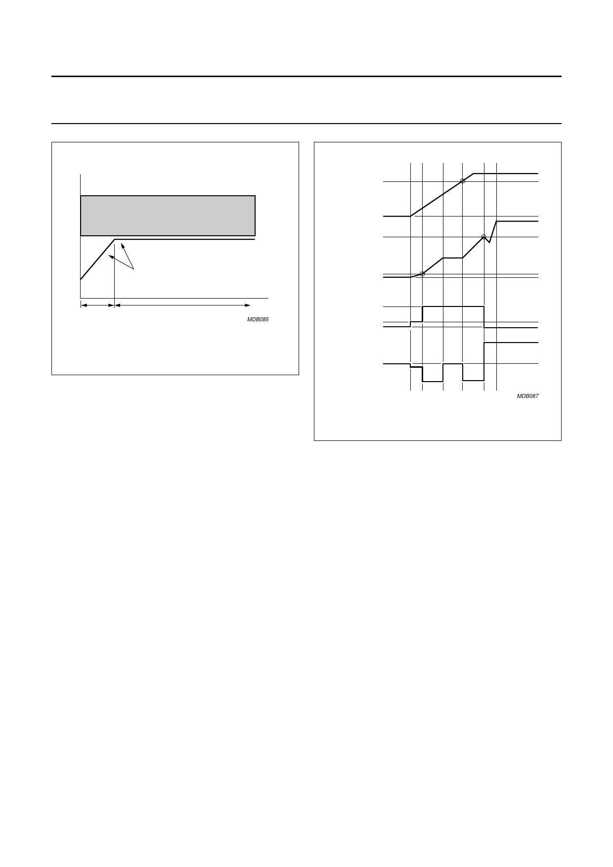
6.1 Start-up, mains voltage-dependent
operation-enabling level and undervoltage
lock-out
Initially, the IC is supplied by the rectified mains voltage at
pin VIN. When the voltage at pin VCC is below the VCC
voltage for VIN current trip level VCC(trip)(VIN), the supply
current drawn from pin VIN, (IVIN) is at the low value
IVIN(min). When VCC rises to the VCC(trip)(VIN) level, the
current at pin VIN changes to the high value IVIN(max).
When the voltage at pin VIN is below the mains
voltage-dependent operation-enabling level (M-level), the
IC supply capacitor CVCC is charged by the internal
start-up current source to approximately 5 V. When the
voltage at pin VIN exceeds the M-level, the start-up
current source continues to charge CVCC (switch S1 open;
see Fig.2).
When VCC reaches the start-up voltage level VCC(start), the
IC switches to high efficiency (green function) operation by
no longer drawing current from pin VIN (see Fig.5).
At VCC(start) the IC activates the external MOSFET. When
the voltage across the auxiliary winding rises above the
voltage across CVCC, the IC supply current will be supplied
by the auxiliary winding via pin VCC.
If the voltage on pin VCC falls below the VCC undervoltage
lock-out level VCC(UVLO), the IC stops switching and enters
a safe restart mode in which current to the IC is supplied
by the rectified mains voltage via pin VIN, and CVCC is
re-charged by the internal start-up current source to
VCC(start).
Fig.5 Start-up sequence.
MDB087
Inhibiting the auxiliary supply by external means causes
the converter to operate in a stable, well-defined burst
mode. This is a burst standby mode that is less efficient
than the normal burst standby mode described in
section 6.12.
If the voltage at pin VIN falls below the mains undervoltage
lock-out level MUVLO, a safe restart mode is activated, and
the IC stops switching.
During normal operation (non-burst standby mode), the
duty cycle of the IC, and thus the output power of the
supply, is regulated by a control voltage at pin CTRL.
If pin VCC is connected to ground, the IC switches to low
power standby operation and the start-up current drawn
via pin VIN reduces to 400 µA (typical). When the voltage
on pin VCC rises above 700 mV (typical), the start-up
current increases to 1 mA (typical).
6.2 Supply management
All internal reference voltages are derived from a
temperature compensated, on-chip bandgap.
2003 Aug 11
7
Share Link: 