TEA1541 Ver la hoja de datos (PDF) - Philips Electronics
Número de pieza
componentes Descripción
Fabricante
TEA1541 Datasheet PDF : 19 Pages
| |||
Philips Semiconductors
SMPS control IC with
synchronization function
Product specification
TEA1541
5 PINNING
SYMBOL
VCC
GND
CTRL
DEM
Isense
DRIVER
HVS
VIN
PIN
DESCRIPTION
1 supply voltage
2 ground
3 control input
4 input from auxiliary winding
for demagnetization timing,
OVP and overpower
protection (OPP)
5 programmable current sense
input
6 gate driver output
7 high voltage safety spacer,
not connected
8 input for start-up current and
mains voltage recognition
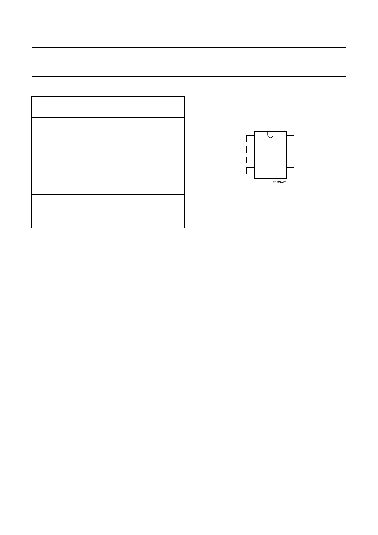
handbook, halfpage
VCC 1
8 VIN
GND 2
7 HVS
TEA1541P
CTRL 3
6 DRIVER
DEM 4
5 Isense
MDB084
Fig.3 Pin configuration.
6 FUNCTIONAL DESCRIPTION
The TEA1541 is intended as the controller for a compact
flyback converter for CRT monitor applications. The IC is
situated on the primary side of the output transformer.
Output power is determined by the current in the primary
winding. The voltage across an auxiliary winding in the
transformer is converted to a current by resistor RDEM and
used by the IC to derive the current in the primary winding.
This winding is also used for continuous mode protection,
overvoltage protection, and to power the IC after start-up.
The IC can operate in either synchronized or
unsynchronized mode. In synchronized mode, the IC
synchronizes the converter switching frequency to the
monitor line frequency to prevent interference.
Line synchronizing pulses are applied to pin CTRL.
Each operating cycle of the converter comprises a primary
stroke followed by a secondary stroke. During the primary
stroke, current flows in the primary winding.
The secondary stroke transfers the energy stored in the
transformer core to the secondary winding. In either
synchronized or unsynchronized mode, the primary stroke
only starts at the end of the secondary stroke when the
transformer is demagnetized to ensure zero switching
primary current. If no synchronizing pulses are present
(unsynchronized mode), the IC will operate at its minimum
switching frequency.
The IC has an internal frequency divider which allows it to
operate in synchronized mode at a lower frequency than
the synchronizing pulses supplied to pin CTRL by the
application. The limited frequency range allows an
economical design of the transformer.
In unsynchronized mode, when the power that is drawn
from the converter decreases, the converter switching
frequency also decreases. At very low power (standby)
levels, the frequency of the VCO decreases from 25 kHz
to the minimum value of approximately 6 kHz as shown by
the slope of Fig.4. In a typical application it is possible to
obtain an input power of less than 3 W with an output
power of 100 mW.
2003 Aug 11
6
Share Link: 