TEA1205 Ver la hoja de datos (PDF) - Philips Electronics
Número de pieza
componentes Descripción
Fabricante
TEA1205 Datasheet PDF : 16 Pages
| |||
Philips Semiconductors
High efficiency DC/DC converter
Preliminary specification
TEA1205AT
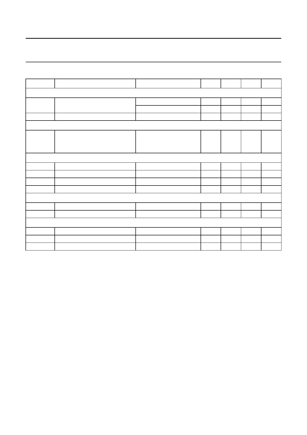
QUICK REFERENCE DATA
SYMBOL
PARAMETER
CONDITIONS
MIN. TYP. MAX. UNIT
Supplies
VO
Vstart
output voltage
start-up voltage
VSEL = LOW
VSEL = HIGH
5.23 5.55 5.85 V
3.13 3.34 3.54 V
1.6
2.0
2.2
V
Efficiency; see Figs 6 and 7
η
efficiency
up from 2.4 to 3.3 V
up from 3.6 to 5.5 V
1 mA < IL < 1.0 A
1 mA < IL < 1.0 A
80
90
95
%
83
90
94
%
Current levels
Iq
ISHDWN
IlimN
Ilx
quiescent current at pin 3
shut-down current
NFET current limit
max. continuous current at pin 5
note 1
50
60
−
2
0.9 Ilim Ilim
−
−
70
µA
10
µA
1.1 Ilim A
1.0
A
Power MOSFETS
RdsON(N)
RdsON(P)
pin-to-pin resistance NFET
pin-to-pin resistance PFET
0.08 0.12 0.20 Ω
0.10 0.16 0.25 Ω
Timing
fsw
switching frequency
tres
response time from standby to Pmax
fsync
synchronisation input frequency
150 200 240 kHz
−
25
−
µs
−
13
−
MHz
Note
1. The NFET current limit is set by an external 1% accurate resistor Rlim connected between pin 7 and pin 6 (ground).
The typical maximum instantaneous current is defined as: Ilim = 890 V/ Rlim so the use of Rlim = 315 Ω will lead to a
typical maximum current value of 2.83 A. The average inductor current during current limit also depends on
inductance value and resistive losses in all components in the power path. In normal application and when using
Rlim = 315 Ω, the average inductor current will be limited to 2.3 A typical.
1998 Mar 24
3
Share Link: 