TDF5140 Ver la hoja de datos (PDF) - Philips Electronics
Número de pieza
componentes Descripción
Fabricante
TDF5140 Datasheet PDF : 19 Pages
| |||
Philips Semiconductors
Brushless DC motor drive circuit
Product specification
TDF5140A
SYMBOL
PARAMETER
CONDITIONS
MIN. TYP.
CAP-CD
Isink
Isource
Isink/Isource
VIL
VIH
output sink current
output source current
ratio of sink to source current
LOW level input voltage
HIGH level input voltage
10.6 16.2
−5.3 −8.1
1.85 2.05
850 875
2.3
2.4
CAP-DC
Isink
Isource
Isink/Isource
VIL
VIH
output sink current
output source current
ratio of sink to source current
LOW level input voltage
HIGH level input voltage
10.1
−20.9
0.9
850
2.3
15.5
−15.5
1.025
875
2.4
Notes
1. An unstabilized supply can be used.
2. VVMOT = VP, all other inputs at 0 V; all outputs at VP; IO = 0 mA.
3. Switching levels with respect to MOT1, MOT2 and MOT3.
4. Drivers are in the high-impedance OFF-state.
5. The outputs are short-circuit protected by limiting the current and the IC temperature.
MAX.
22
−11
2.25
900
2.55
20.9
−10.1
1.15
900
2.55
UNIT
µA
µA
mV
V
µA
µA
mV
V
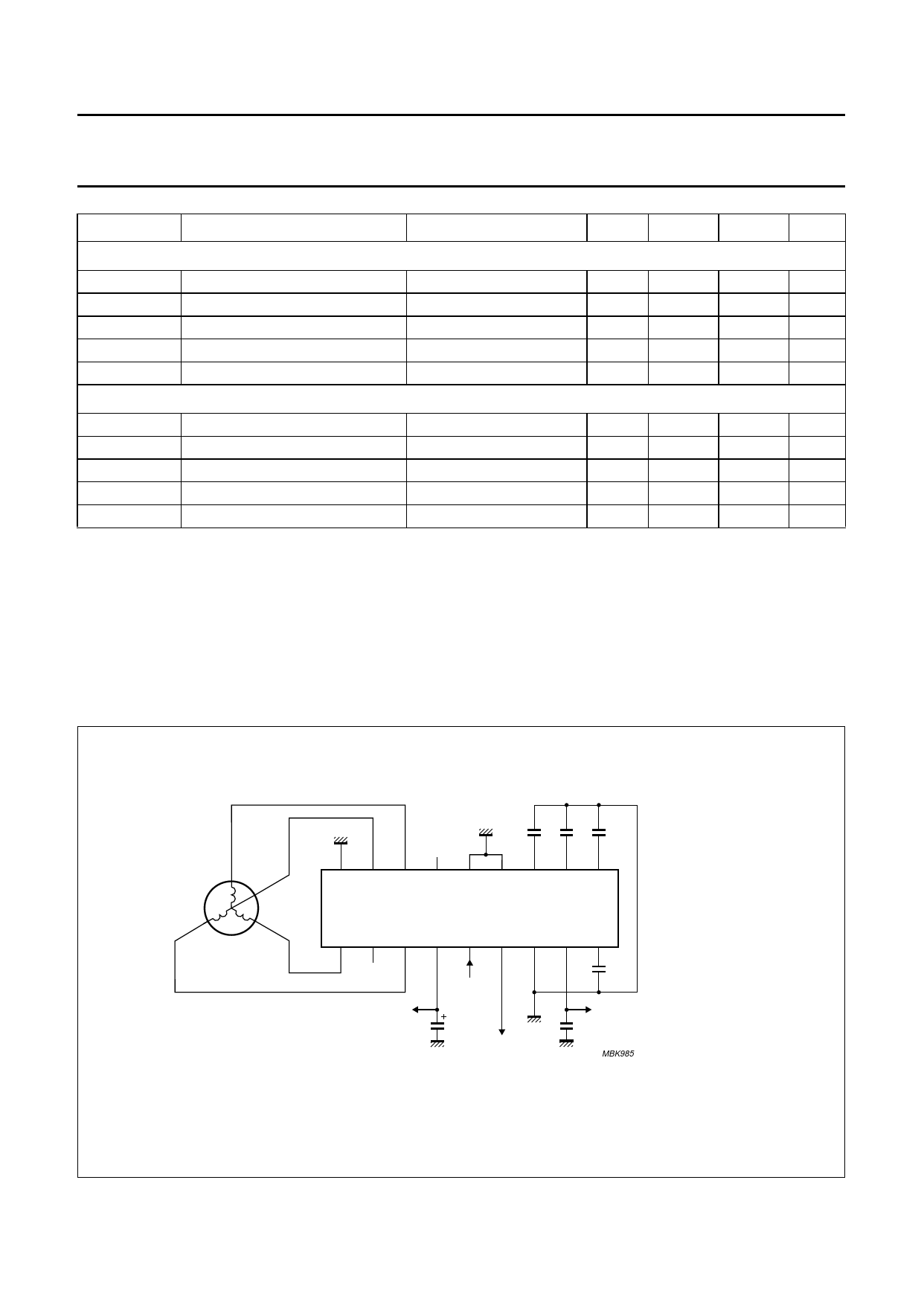
APPLICATION INFORMATION
k, full pagewidth
(1)
GND1
10 220 18 nF
nF nF
18 17 16 15 14 13 12 11 10
TDF5140A
123456789
(1) Value selected for 3 Hz
start-up oscillator frequency
VMOT
PGIN
10 µF
PG/FG
18 nF
VP
MBK985
(1) Value selected for 3 Hz start-up oscillator frequency.
Fig.4 Application diagram without use of the operational transconductance amplifier (OTA).
1999 March 15
9
Share Link: 