TDA9108 Ver la hoja de datos (PDF) - STMicroelectronics
Número de pieza
componentes Descripción
Fabricante
TDA9108 Datasheet PDF : 9 Pages
| |||
TDA9108
APPLICATION INFORMATION
Sync Extractor and Polarity Detection
This circuit is able to handle both positive or nega-
tive TTL input signal on Pin 9. The voltage on Pin
10 drives an internal inverter providing a constant
sync polarity to the 1st phase comparator.
When using a RC network between Pin 9 and 10
(see Typical Application), the IC will adapt itself
automatically to positive or negative sync. On an
other hand, and in order to simplified the applica-
tion, the Pin 10 can be connected to ground or
supply (through a resistor), in this case the IC will
work only with one sync polarity.
1st PLL
It is composed by a phase comparator, the oscilla-
tor and an external loop filter (see Figure 2)
- The phase comparator receives the H-sync sig-
nal (with positive polarity) and a signal coming
from the internal current controlled oscillator. The
loop is closed through an external resistor be-
tween Pin 11 and 13.
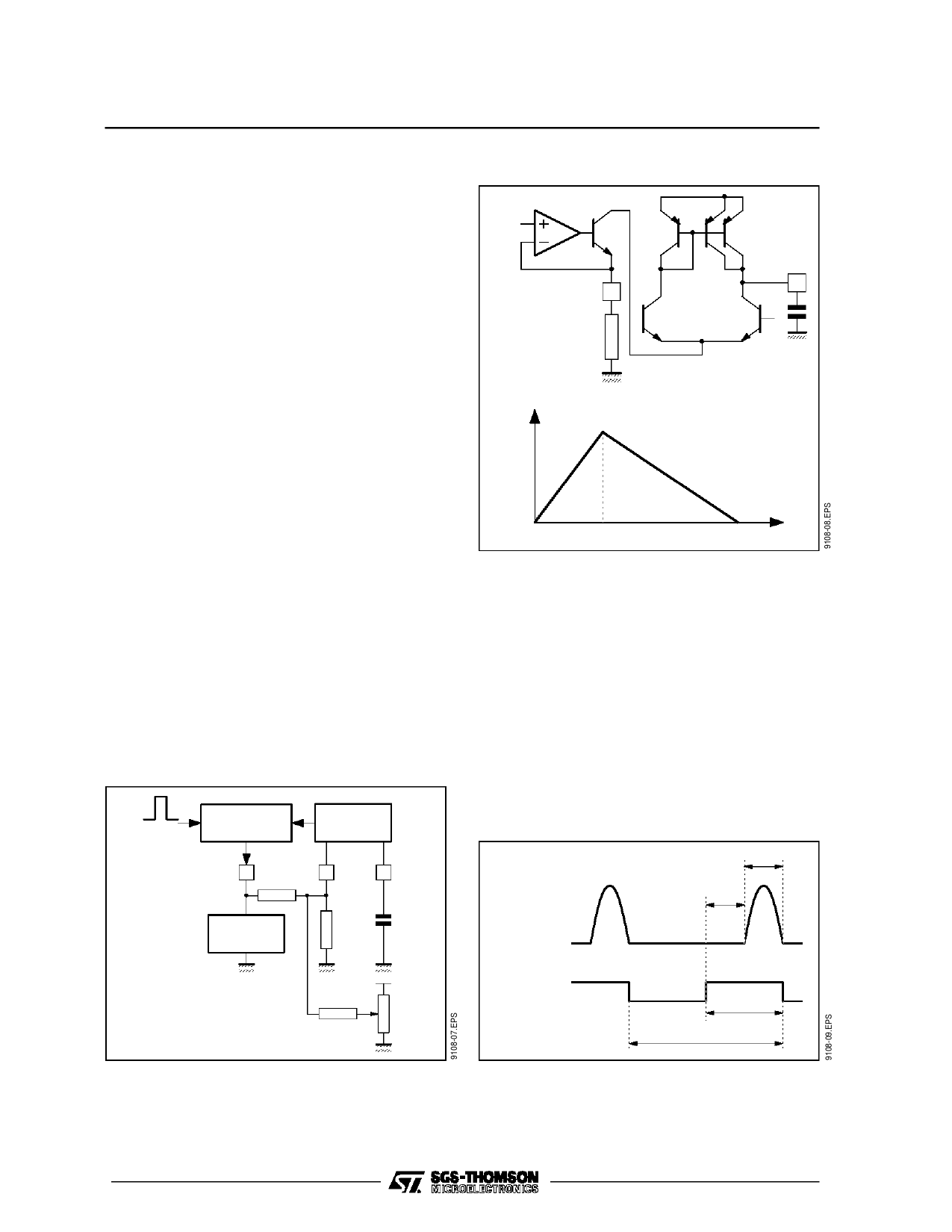
- The oscillatorgenerates a sawtooth waveform on
Pin 12 by charging and discharging the external
capacitor. The capacitor is discharging by the
current flowing Pin 13 and charged by two times
this latter (see Figure 3).
The sawtooth is used internally to generate all the
required timings.
It is possible to DC control the frequency by adding
or substracting a DC current on Pin 13 (see Fig-
ure 2).
Figure 2
H-sync
PHASE
COMPARATOR
11
VCO
13
12
LOOP
FILTER
Figure 3
VREF
12
13
Pin 12
1/3T
T
2nd Phase Locked Loop
To compensate the delay introduced by the hori-
zontal final stage, the flyback pulse (Pin 6) and the
oscillator waveform (Pin 12) are compared in the
2nd phase comparator. The result of the compari-
son is a control current which, after it has been
filtered by the external capacitor on Pin 5, is sent
to a phase shifter which adequately regulates the
horizontal output pulses phase.
The maximum phase shift allowed is td = tp - tf
where tf is the flyback duration (see Figure 4).
If td > tp - tf, then the horizontal output transistor will
be tunned on during flyback distroying it.
Figure 4
tf
td
HORIZONTAL
FLYBACK
R1
P1
HORIZONTAL
DRIVE
BU OFF
BU ON
tp
HP
7/9
Share Link: 