TDA9108 Ver la hoja de datos (PDF) - STMicroelectronics
Número de pieza
componentes Descripción
Fabricante
TDA9108 Datasheet PDF : 9 Pages
| |||
TDA9108
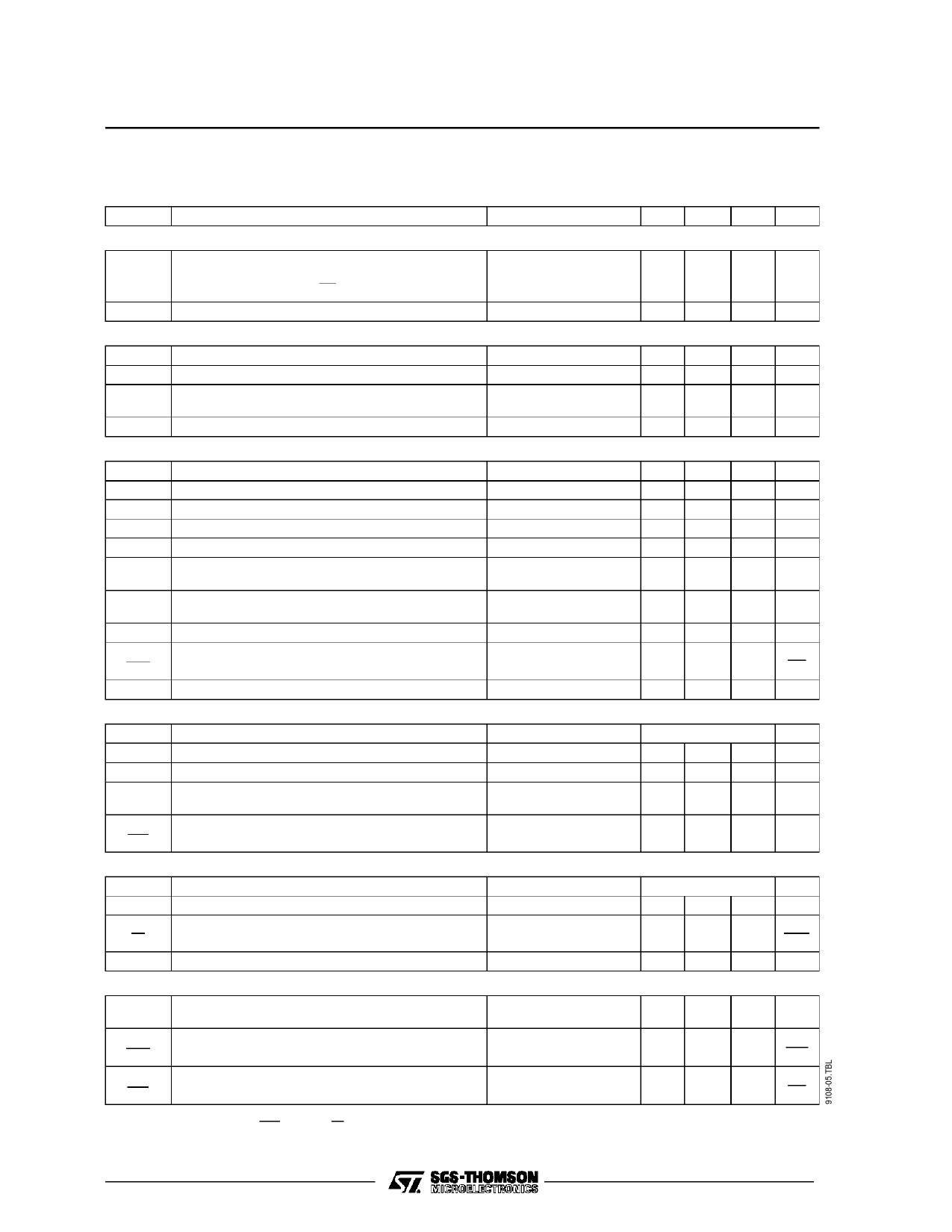
ELECTRICAL CHARACTERISTICS (continued)
(refer to the test circuit, VS = 12V, TA = 25oC, unless otherwise specified)
Symbol
Parameter
Test conditions
Min. Typ. Max.
DUTY CYCLE ADJUSTMENT (continued)
tpADJ
K4
Max. Horizontal Output Duty Cycle Range
(function
of
V4)
tp
=
K4 ⋅
V4
VS
(see
note
3)
Duty Cycle Adjustment Coefficient
f = 31.5kHz
50
1.6 1.8 2
KEY PULSE OUTPUT
V7k Key Pulse Output Peak Voltage (emitter follower)
V7L Low Level (outside the key pulse)
tSK Phase Relation between Trailing Edge of Key
Pulse and Middle of Sync. Input Pulse
tK Key Pulse Duration
OSCILLATOR
I7 = 5mA
f = 31.5kHz
Sync width = 2µs
4
5
0.2 0.5
1.1 1.5 1.9
1.25 1.7 2.15
V12 Low Level Threshold Voltage
V12 High Level Threshold Voltage
I12 Charge Current
I12 Discharge Current
V13 Reference Voltage on Pin 13
fO Free Running Frequency
fMax. Maximum Oscillator Frequency
Jitt. Horizontal Jitter
∆fO Frequency Control Sensitivity
∆I13
∆fO Frequency Change when VS Drops to 7.5V
PHASE COMPARATOR
R13 = 10kΩ
R13 = 10kΩ
R13 = 10kΩ
C12 = 2.2nF
R13 = 47kΩ
C12 = 2.2nF
f = 31.5kHz
R13 = 10kΩ
C12 = 2.2nF
5.4
8.2
0.6
0.3
2.6 2.9 3.2
27 30 33
66
5
100
-6
V5 Control Voltage Range
I5 Peak Control Current
I5 Input Current (blocked Phase Detector)
tD Permissible Delay between Output Pulse Leading
Edge and Flyback Pulse Leading Edge
∆t Static Control Error
∆tD
SYNC PULSE-OSCILLATOR PHASE COMPARATOR
During flyback pulse
Outside flyback pulse
9.4 to 8.2
± 0.85
5
tp - tf
0.2
V11 Control Voltage Range
I11 Control Peak Current
∆f Phase Lock Loop Gain
∆t
f
Catching and Holding Range
During Sync Pulse
R11-13 = 100kΩ
See Typical Application
4.6 to 1.4
± 2.3
4
± 700
OVERALL PHASE RELATIONSHIP
tO Phase Relation between Middle of Flyback Pulse R13 = 10kΩ
1.1
and Middle of Sync. Pulse
C12 = 2.2nF
∆V5
∆tO
Adjustment Sensitivity
130
∆I5
∆tO
Adjustment Sensitivity
50
Note 3 :
td must be ≥
(Hperiod
1t0p0
−
0.25
−
tfly)
2
in
order
to
have
±
5%
horizontal
phase
adjustment
range.
Unit
%
V
V
µs
µs
V
V
mA
mA
V
kHz
kHz
ns
Hz
µA
%
V
mA
µA
µs
%
V
mA
kHz
µs
Hz
µs
mV
µs
µA
µs
4/9
Share Link: 