TDA8380A Ver la hoja de datos (PDF) - Philips Electronics
Número de pieza
componentes Descripción
Fabricante
TDA8380A Datasheet PDF : 20 Pages
| |||
Philips Semiconductors
Control circuit for switched mode power supplies
Product specification
TDA8380A
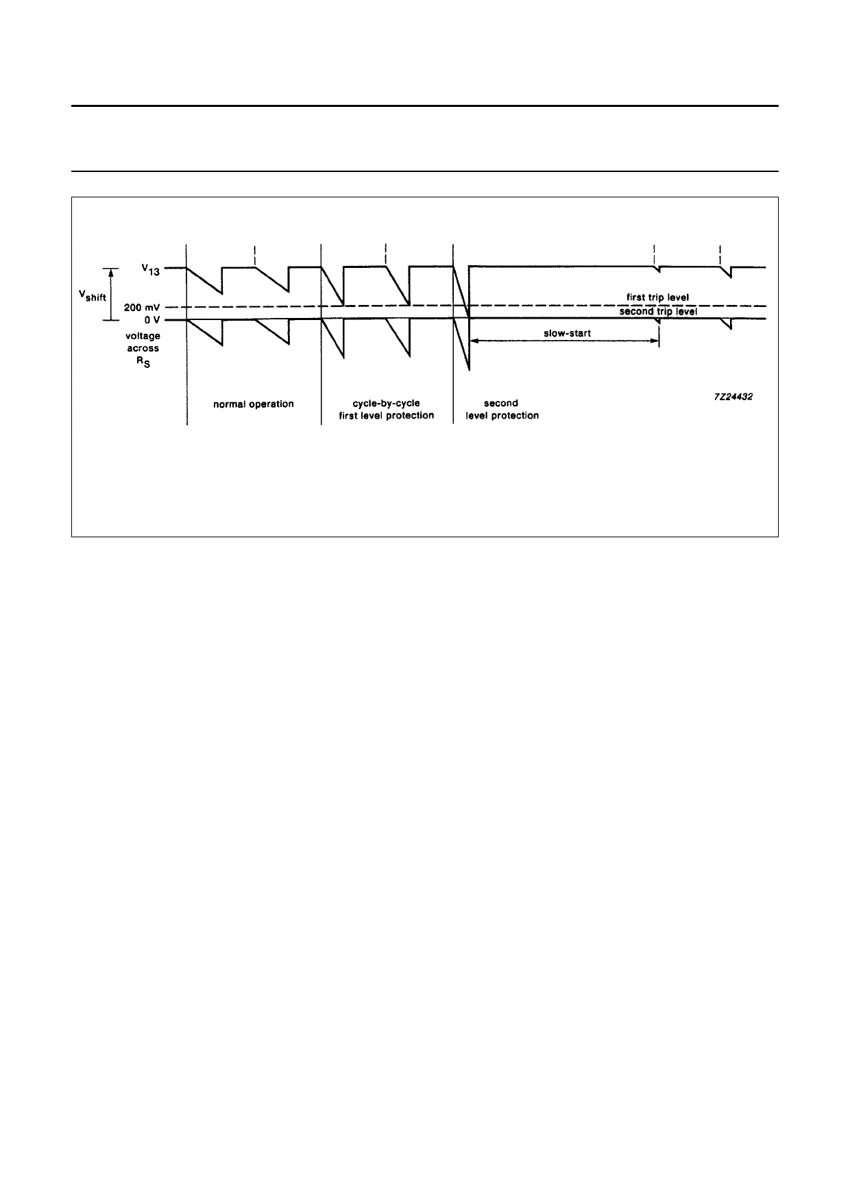
Fig.10 Current protection.
Slow-start circuit
A slow-start occurs:
• At Switch-on of the SMPS
• After a current trip as described in the section Over-current protection
• After a low or high VCC trip.
The capacitor at the SS input is discharged and the slow-start bistable is reset when the voltage at the SS input falls
below 0.5 V after which the circuit is ready for a slow-start. The dead time (during which the capacitor at the SS input is
being charged to the 1.4 V lower level of the sawtooth) before duty cycle regulation starts is minimal. The SS input can
also be used for Dmax setting by connecting a resistor to ground. The voltage across this resistor is then limited to
1/6 × Vref × R12/R6.
Output stages
The output stage consists of two NPN darlington transistors, their collector and emitter connected to separate pins (see
Fig.13). The top transistor is capable of sourcing a maximum of 0.75 A to the high-voltage transistor while the bottom
transistor can sink peak currents up to 2.5 A.
For low currents up to 10 mA, the saturation voltage of the sink darlington transistor is similar to that of a single transistor
(see Fig.11). During switching of this transistor dV/dt is internally limited to reduce interference.
Care should be taken with the external wiring of the output pins to avoid oscillation or interference due to parasitic
inductance and wire resistance.
During start-up a small current flows from VCC to E2 to precharge the series capacitor at the output (see Fig.13).
November 1993
11
Share Link: 