TDA7300 Ver la hoja de datos (PDF) - STMicroelectronics
Número de pieza
componentes Descripción
Fabricante
TDA7300 Datasheet PDF : 16 Pages
| |||
TDA7300
APPLICATION INFORMATION (continued)
SERIAL BUS INTERFACE
S-BUS Interface and I2CBUS Compatibility
Data transmission from microprocessor to the
TDA7300 and viceversa takes place thru the 3-
wire S-BUS interface, consisting of the three lines
SDA, SCL, SEN. If SDA and SEN inputs are
short-circuited together, then the TDA7300 ap-
pears as a standard I2CBUS slave.
According to I2CBUS specification the S-BUS
lines are connected to a positive supply voltage
via pull-up resistors.
LOW transition of the SDA line while SCL is
HIGH. The stop condition is a LOW to HIGH tran-
sition of the SDA line while SCL is HIGH.
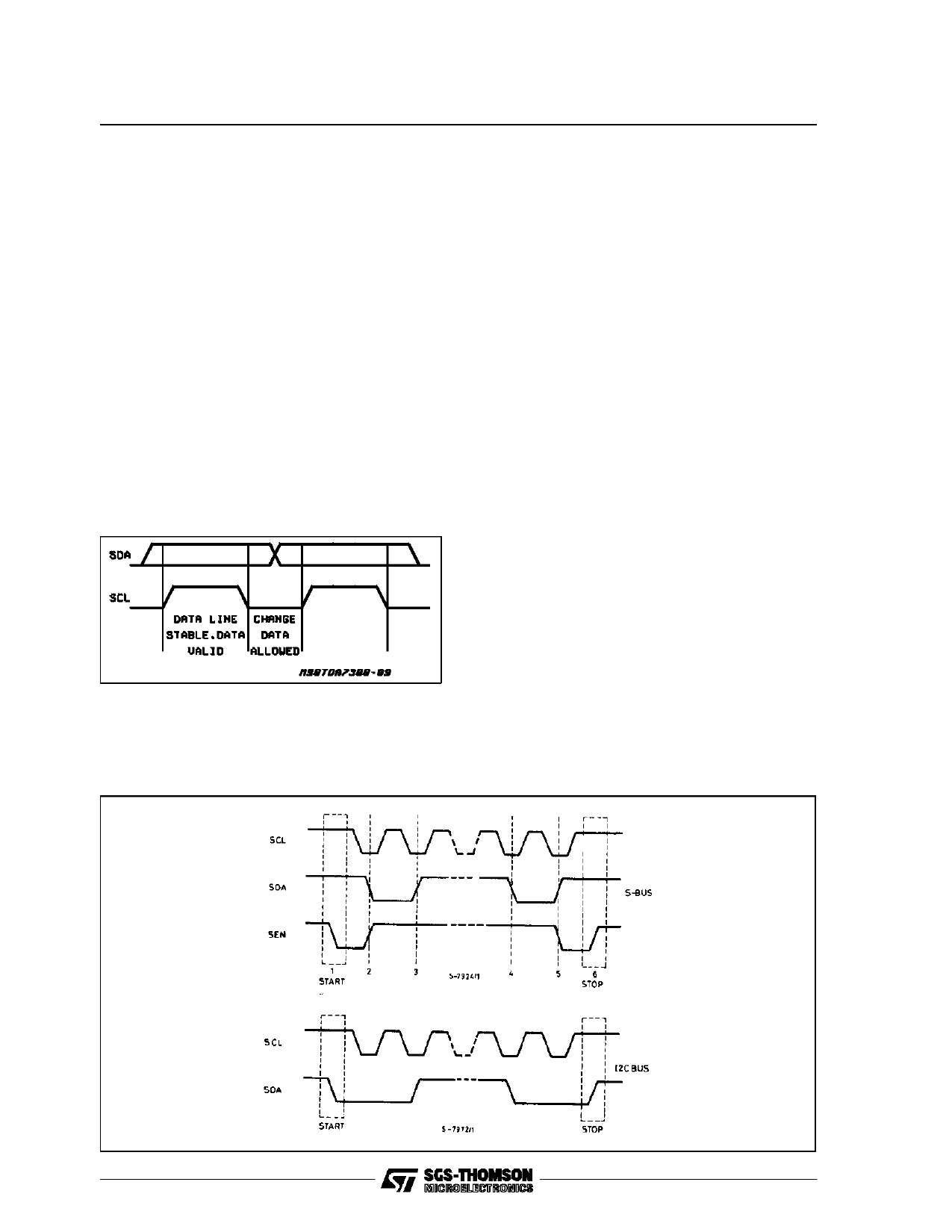
S-bus:
the start/stop conditions (points 1 and 6) are de-
tected exclusively by a transition of the SEN line
(1 → 0 / 0 → 1) while the SCL line is at the HIGH
level.
The SDA line is only allowed to change during the
time the SCL line is low (points 2, 3, 4, 5). After
the start information (point 1) the SEN line returns
to the HIGH level and remains unchanged for all
the time the transmission is performed.
Data Validity
As shown in fig. 21, the data on the SDA line
must be stable during the high period of the clock.
The HIGH and LOW state of the data line can
only change when the clock signal on the SCL
line is LOW.
Figure 21: Data Validity on the I2CBUS
Start and Stop Conditions
I2CBUS:
as shown in fig.22 a start condition is a HIGH to
Figure 22: Timing Diagram of S-BUS and I2CBUS
Byte Format
Every byte transferred on the SDA line must con-
tain 8 bits. Each byte must be followed by an ac-
knowledge bit. The MSB is transferred first.
Acknowledge
The master (µP) puts a resistive HIGH level on the
SDA line during the acknowledge clock pulse (see
fig. 23). The peripheral (audioprocessor) that ac-
knowledges has to pull-down (LOW) the SDA line
during the acknowledge clock pulse, so that the
SDA line is stable LOW during this clock pulse.
The audioprocessor which has been addressed
has to generate an acknowledge after the recep-
tion of each byte, otherwise the SDA line remains
at the HIGH level during the ninth clock pulse
time. In this case the master transmitter can gen-
erate the STOP information in order to abort the
transfer.
10/16
Share Link: 