TDA3617 Ver la hoja de datos (PDF) - Philips Electronics
Número de pieza
componentes Descripción
Fabricante
TDA3617 Datasheet PDF : 16 Pages
| |||
Philips Semiconductors
Multiple voltage regulator
Preliminary specification
TDA3617
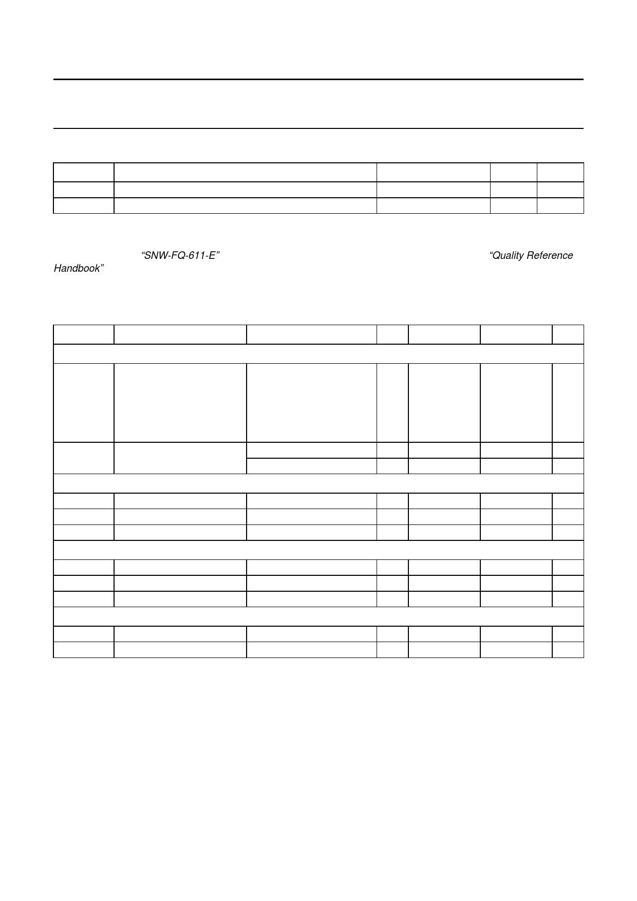
THERMAL CHARACTERISTICS
SYMBOL
Rth(j-c)
Rth(j-a)
PARAMETER
thermal resistance from junction to case
thermal resistance from junction to ambient
CONDITIONS
regulator and switch-on
in free air
VALUE
2
50
UNIT
K/W
K/W
QUALITY SPECIFICATION
In accordance with “SNW-FQ-611-E”. The number of the quality specification can be found in the “Quality Reference
Handbook”.
CHARACTERISTICS
VP = 14.4 V; Tamb = 25 °C; measured in test circuit of Fig.6; unless otherwise specified.
SYMBOL
PARAMETER
CONDITIONS
MIN.
TYP.
Supplies
VP
supply voltage
operating
REGn on
note 1
jump start
t ≤ 10 minutes
load dump protection
for 50 ms; tr ≥ 2.5 ms
Iq
quiescent current
VP = 12.4 V; note 2
VP = 14.4 V; note 2
Power supply Schmitt trigger for regulators 1, 2 and 3
9.5 14.4
6 14.4
−
−
−
−
−
5
−
5
Vthr
rising voltage threshold
Vthf
falling voltage threshold
Vhys
hysteresis
Enable input (regulators 1, 2 and 3)
Ven = 3 V
Ven = 3 V
6.2 6.8
4.0 4.5
1.5 2.3
Vi(off)
off-level input voltage
Vi(on)
on-level input voltage
ILI
input leakage current
Hold buffer
Ven = 5 V
−0.2
−
1.8
5 30
IsinkL
ILO
LOW-level sink current
output leakage current
VHOLD ≤ 0.8 V
VHOLD = 5 V
2
−
−
0
MAX.
17.5
17.5
30
50
40
−
7.5
5.0
3.0
+1.2
−
50
−
5
UNIT
V
V
V
V
µA
µA
V
V
V
V
V
µA
mA
µA
1999 Jul 14
6
Share Link: 