TD340 Ver la hoja de datos (PDF) - STMicroelectronics
Número de pieza
componentes Descripción
Fabricante
TD340 Datasheet PDF : 21 Pages
| |||
TD340
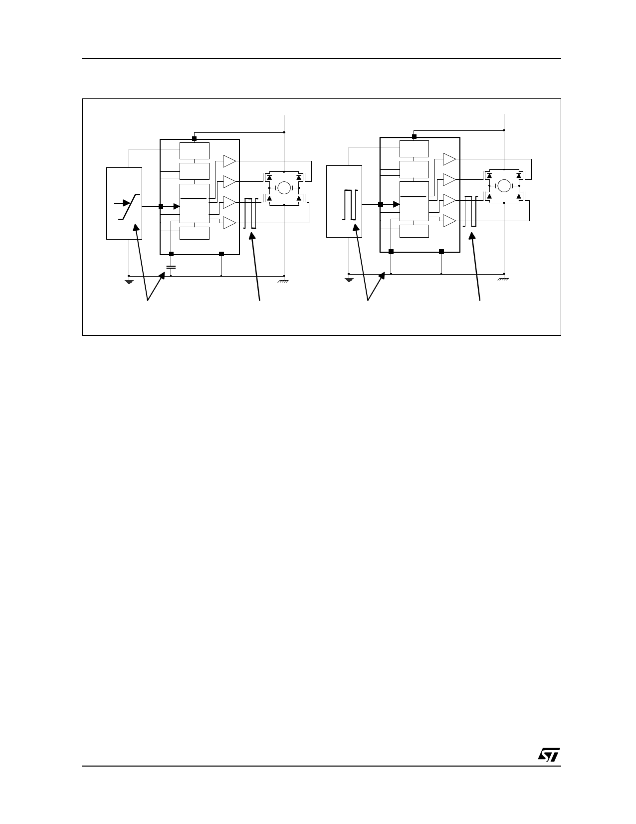
Figure 2 : PWM Analog and Digital Modes
TD340
µP
5V
IN1
0V
PWM
PWM
Vbatt
µP
TD340
M
5V
IN1 PWM
PWM
0V
CF
CF
Vbatt
M
ANALOG INPUT
+ CF (270pF)
PWM OUTPUT
DIGITAL INPUT
+ CF GROUNDED
PWM OUTPUT
Active (synchronous) rectification for free-wheel current
A motor is an inductive load. When driven in PWM mode, motor current is switched on and off at the
25kHz frequency. When the MOS is switched off, current can not instantaneously drop to zero, a so-called
"free-wheel" current arises in the same direction than the power current. A path for this current must be
provided, otherwise high voltage could arise and destroy the component. The classical way to handle this
situation is to connect a diode in an anti-parallel configuration regarding to the MOS, so that current can
continue to flow through this diode, and finally vanishes by the means of ohmic dissipation, mainly in the
diode due to its 0.8V direct voltage. For high currents, dissipation can be an important issue (eg: 10A x
0.8V makes 8 W!). Furthermore, high speed diodes have to be used, and are expensive.
A more efficient way to handle this problem is to use the high side MOS as a synchronous rectifier. In this
mode, the upper MOS is switched ON when the lower one is switched OFF, and carries the free-wheel
current with much lower ohmic dissipation. Advantages are : one expensive component less (the fast
power diode), and more reliability due to the lower dissipation level.
However, we have to take care not to drive the two MOS simultaneously. To avoid transient problems
when the MOS are switched, a deadtime is inserted between the opening of one MOS, and the closing of
the other one. In the TD340 device, the deadtime is fixed to about 2.5 microseconds. This value is the time
between the commands of the gate drivers, not the deadtime between the actual MOS states because of
the rising and falling times of the gate voltages (due to capacitance), and the MOS characteristics. The
actual value of the deadtime for a typical configuration is about 1.5 microseconds.
Figure 3 shows the synchronous rectification principle
Table 1 summarizes the status of the Mosfets (and the speed and direction of the motor) according to the
Inputs (IN1 and IN2) status in analog and logic modes.
8/21
Share Link: 