TCL1585 Ver la hoja de datos (PDF) - TelCom Semiconductor Inc => Microchip
Número de pieza
componentes Descripción
Fabricante
TCL1585
TelCom Semiconductor Inc => Microchip

TCL1585 Datasheet PDF : 13 Pages
| |||
PRELIMINARY INFORMATION
TCL1584
TCL1585
TCL1587
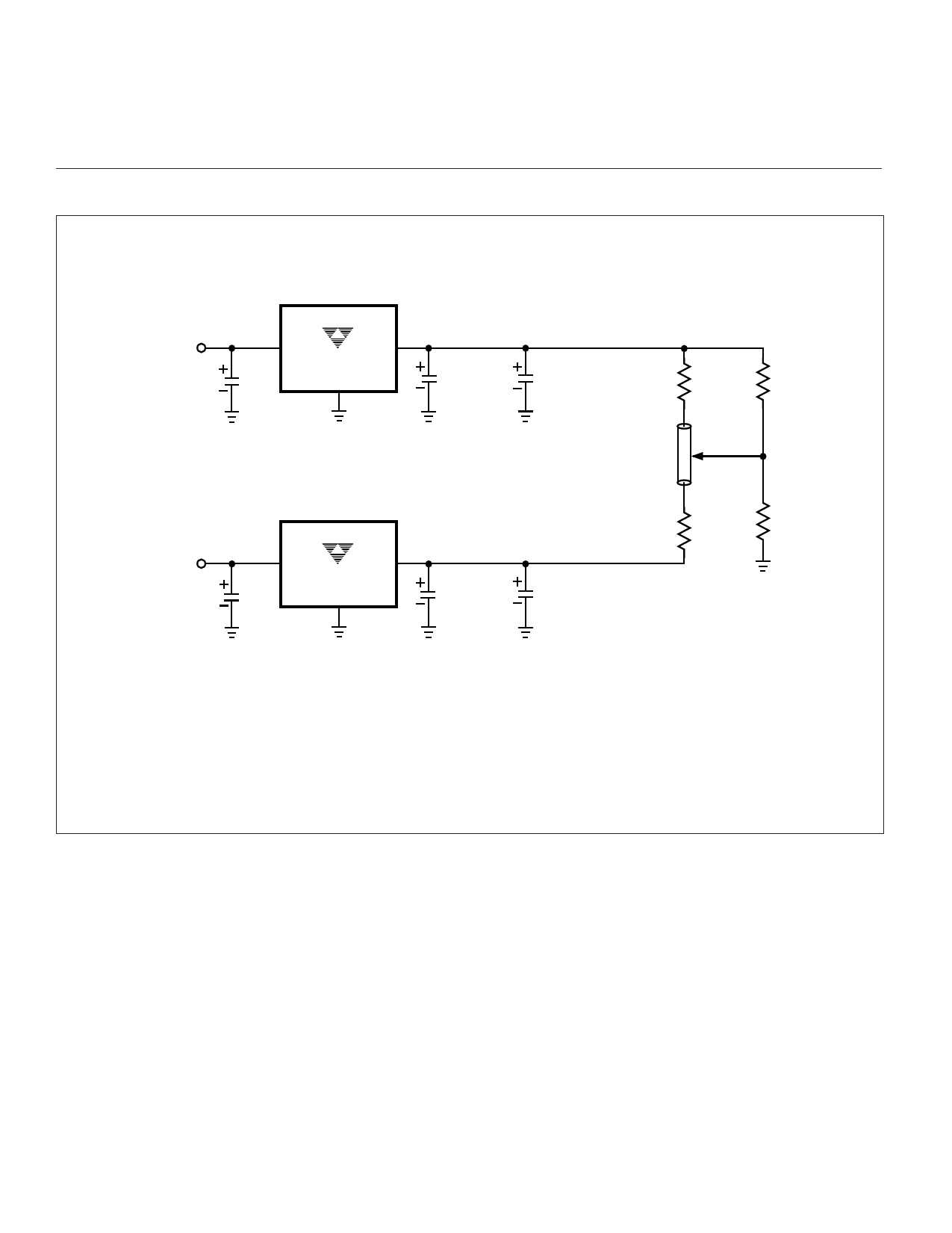
TYPICAL APPLICATIONS (Cont.)
7A / 5A / 4.6A / 3A, FAST RESPONSE,
LOW DROPOUT POSITIVE LINEAR
VOLTAGE REGULATORS
Typical Intel™* Pentium™* Pro GTL+ Bus Terminator Application Using TCL1587-1.5
VIN = 5V or 3.3V
C1 = 10µF
VIN = 5V or 3.3V
C1 = 10µF
VIN
VOUT
TCL1587-1.5
GND
VOUT = 1.5V @ 3A
C2 = 10µF
(Tantalum)
RTERM
C3 =1µF x 5 = 100Ω x 71
(Ceramic) Lines
RREF
VIN
VOUT
TCL1587-1.5
GND
GTL+ Bus (ZO)
VREF = 1.0V
VOUT = 1.5V @ 3A
RTERM
= 100Ω x 71
Lines
C2 = 10µF
(Tantalum)
C3 = 1µF x 5
(Ceramic)
2RREF
NOTES: 1. It is recommended that the GTL+ bus be terminated at each end by a separate regulator to avoid power distribution losses.
2. The GTL+ bus transmission line symbol will consist of all the components (chip set IC's) on the GTL+ bus.
3. RREF and 2RREF should be chosen such that VREF loading does not appreciably degrade VREF regulation.
Values <100 ohms should suffice for most applications.
4. RTERM will be determined by individual bus physical/electrical parameters. See CPU manufacturer documentation for
application information.
*All Trademarks and Trade Names are the property of their respective owners.
TCL1584/1585/1587-04 6/6/97
10
Share Link: