TC72 Ver la hoja de datos (PDF) - Microchip Technology
Número de pieza
componentes Descripción
Fabricante
TC72 Datasheet PDF : 24 Pages
| |||
TC72
TABLE 3-3: OPERATIONAL MODES
Mode
CE
SCK (Note 1)
SDI
SDO
Disable
L
Input Disabled
Input Disabled
High Z
Write (A7 = 1)
H
CP=1, Data Shifted on Falling Edge,
Data Clocked on Rising Edge
Data Bit Latch
High Z
CP=0, Data Shifted on Rising Edge,
Data Clocked on Falling Edge
Read (A7 = 0)
H
CP=1, Data Shifted on Falling Edge,
Data Clocked on Rising Edge
X
Next data bit shift,
Note 2
CP=0, Data Shifted on Rising Edge,
Data Clocked on Falling Edge
Note 1: CP is the Clock Polarity of the microcontroller system clock. If the inactive state of SCK is logic level high,
CP is equal to ‘1’; otherwise, if the inactive state of SCK is low, CP is equal to ‘0’.
2: During a Read operation, SDO remains at a high impedance (High Z) level until the eight bits of data begin
to be shifted out of the Temperature register.
3.4 Read Operation
The temperature and control register data is outputted
from the TC72 using the CE, SCK and SDO lines.
Figure 3-3 shows a timing diagram of the read opera-
tion. Communication is initiated by the chip enable (CE)
going high. The SDO line remains at the voltage level
of the LSb bit that is outputted and goes to the tri-state
level when the CE line goes to a logic low level.
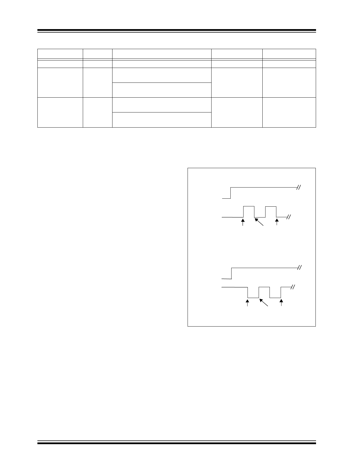
CP = 0
CE
SCK
3.5 Write Operation
Data is clocked into the Control register in order to
enable the TC72’s power saving shutdown mode. The
write operation is shown in Figure 3-3 and is
accomplished using the CE, SCK and SDI line.
SHIFT
EDGE
CLOCK
EDGE
CP = 1
CE
SCK
FIGURE 3-2:
Operation.
SHIFT
EDGE
CLOCK
EDGE
Serial Clock Polarity (CP)
DS21743A-page 10
2002 Microchip Technology Inc.
Share Link: 