TA8051 Ver la hoja de datos (PDF) - Toshiba
Número de pieza
componentes Descripción
Fabricante
TA8051 Datasheet PDF : 9 Pages
| |||
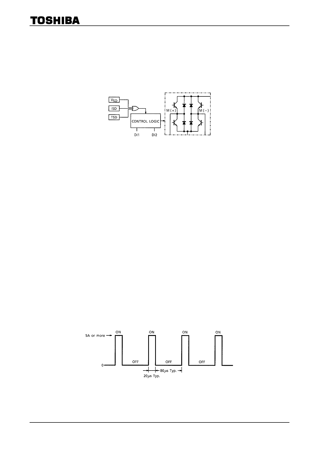
DESCRIPTION OF MULTI-PROTECTIVE OPERATION
TA8051P
The TA8051P has functions for protection from overvoltage (VSD) , overcurrent (ISD) , and overheat (TSD) .
These functions protect the IC (and the motor load in some cases) from deterioration or destruction due to
power-related overstress.
The three functions work independently.
Each function is explained below.
1. Overvoltage protection (VSD)
· Basic operation
When the voltage supplied to the VCC pin is up to the VSD detection voltage, the output is controlled by the
input signals. However, when the VCC voltage exceeds the detection voltage, the output enters
high-impedance state regardless of the input signals.
· Detailed explanation
The VSD voltage is detected by comparing the Zener voltage with the voltage obtained by dividing VCC with
a resistor. When the center voltage of the resistor is higher than the Zener voltage, a transistor-off
instruction is issued to the control logic. When it is lower than the Zener voltage, the logic is controlled by
the input signals from pins 1 and 2.
2. Overheat protection (TSD)
· Basic operation
When the junction (chip) temperature is up to the TSD detection temperature, the output is controlled by the
input signals. When it exceeds the TSD detection temperature, the output enters high-impedance state
regardless of the input signals.
· Detailed explanation
The temperature is detected by monitoring VF of a diode on the chip. When the diode VF is lower than the
internal reference voltage, an output transistor-off instruction is issued to the control logic. When it is higher
than the internal reference voltage, the logic is controlled by the input signals from pins 1 and 2.
3. Overcurrent protections (ISD)
· Basic operation
When the output current (pin 4 or 8, Isink or Isource) is up to the ISD detection current, the output is
controlled by the input signals. When it exceeds the detection current, the output assumes a switching
waveform as shown in Fig.1.
Fig.1 Basic Operation
3
2002-02-27
Share Link: 