TA58L09SQ Ver la hoja de datos (PDF) - Toshiba
Número de pieza
componentes Descripción
Fabricante
TA58L09SQ Datasheet PDF : 12 Pages
| |||
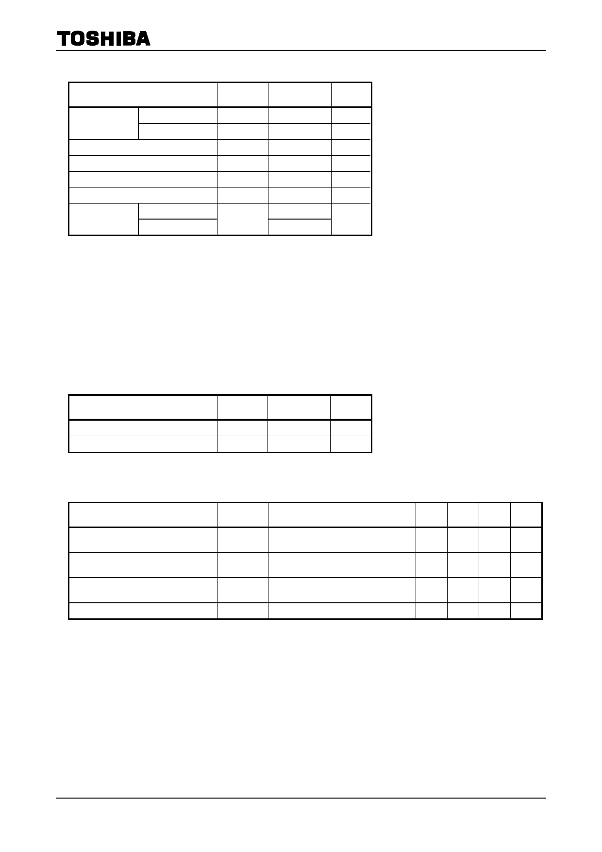
Absolute Maximum Rating (Ta = 25°C)
TA58L05, 06, 08, 09, 10, 12, 15S
Characteristic
Symbol
Rating
Unit
Input voltage
DC
Pulse
Output current
Operating temperature
Junction temperature
Storage temperature
Power dissipation
Ta = 25°C
Tc= 25°C
VIN (DC)
29
V
VIN (Pulse) 60(τ=200ms)
V
IOUT
250
mA
Topr
−40~105
°C
Tj
150
°C
Tstg
−55~150
°C
2
PD
W
20
Note 3: Do not apply current and voltage (including reverse polarity) to any pin that is not specified.
Note 4: Using continuously under heavy loads (e.g. the application of high temperature/current/voltage and the
significant change in temperature, etc.) may cause this product to decrease in the reliability significantly
even if the operating conditions (i.e. operating temperature/current/voltage, etc.) are within the absolute
maximum ratings and the operating ranges.
Please design the appropriate reliability upon reviewing the Toshiba Semiconductor Reliability Handbook
(“Handling Precautions”/Derating Concept and Methods) and individual reliability data (i.e. reliability test
report and estimated failure rate, etc).
Thermal Characteristics
Characteristic
Thermal resistance, junction to ambient
Thermal resistance, junction to case
Symbol
Rth (j−a)
Rth (j−c)
Max
62.5
6.25
Unit
℃/ W
℃/ W
Protection Function (Reference)
Characteristic
Symbol
Test Condition
Min Typ. Max Unit
Thermal shutdown
Peak circuit current
Short circuit current
Overvoltage protection
TSD
I PEAK
I SC
VIN
VIN = 14 V (05~06S)/ 16 V (08~10S)/
18 V (12S)/ 20 V (15S)
VIN = 14 V (05~06S)/ 16 V (08~10S)/
18 V (12S)/ 20 V (15S), Tj = 25°C
VIN = 14 V (05~06S)/ 16 V (08~10S)/
18 V (12S)/ 20 V (15S), Tj = 25°C
Tj = 25°C
⎯ 170 ⎯
°C
⎯
600
⎯
mA
⎯
330
⎯
mA
29
33
⎯
V
Note4: Ensure that the devices operate within the limits of the maximum rating when in actual use.
Note5: When the input voltage exceeds 29 V, the overvoltage protection circuit is activated to turn off
the output voltage.
3
2006-11-02
Share Link: 