TA2024C Ver la hoja de datos (PDF) - Unspecified
Número de pieza
componentes Descripción
Fabricante
TA2024C Datasheet PDF : 18 Pages
| |||
Tripath Technology, Inc. - Technical Information
In most cases, the pop caused by the output offset is not objectionable. But in those cases that
there is concern about the residual pop, the offset can be nulled. There are several ways to trim
the offset. These include using a trim pot, with current limiting resistor, using an active DC servo
comprised of op-amps, resistors and switches, and finally, a look-up table of resistor values
attached to the input. The last scheme is implemented on the EB-TA2024C. Please refer to the
EB-TA2024C document at www.tripath.com for additional information on this circuit.
Please note that while a DC servo is automatic, and thus, does not require manual adjustment, it
is not the best solution. This is because the DC servo has to be slow enough so as not to react to
low frequency audio signals. Thus, it is not possible for such a circuit to eliminate a mute off pop
caused by DC offset. The servo is effective for eliminating mute on pops, since the DC offset
would be nulled to zero by the time the TA2024C is muted. A DC servo, in conjunction, with a
relay is an effective method for completely eliminating mute off and mute on pops, but due to the
small residual pop caused by the TA2024C offset, it is unlikely that such a sophisticated scheme
would be implemented for high-volume production designs.
Output Voltage Offset
The DC offset voltages that appear at the speaker terminals of a TA2024C amplifier are typically
small and for most applications no DC offset correction is necessary. The TA2024C is 100%
tested to ensure that the differential output DC offset voltage is less than +/-150mV. However
this DC offset can cause a small turn on and turn off pop, depending on the offset value for that
specific IC. Every TA2024C IC will have a different offset voltage for each channel.
If the output offset is deemed unacceptable from a turn on/off pop standpoint, there are three
recommended methods for correcting it. These methods of trimming the offset voltage are
optional and for most cases the additional circuitry is not needed.
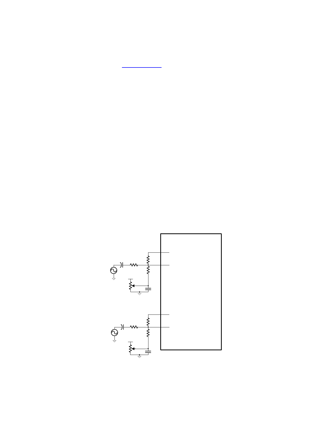
1) A potentiometer can be used at the input of the TA2024C as shown in the figure below. By
changing the input bias voltage the output DC offset voltage can be trimmed. Two separate
potentiometers must be used to trim both channels.
OAOUT1 29
CI
2.2uF
+
RI
RF
20KΩ
20KΩ
INV1 30
V5A (pin 28)
ROFB
1MΩ
ROFA
10KΩ
Offset Trim
Potentiometer
COF
0.1uF
TA2024C
OAOUT2 1
CI
2.2uF
+
RI
RF
20KΩ
20KΩ
INV2 2
V5A (pin 28)
ROFB
1MΩ
ROFA
10KΩ
Offset Trim
Potentiometer
COF
0.1uF
11
TA2024C –KL/1.0/01.06
Share Link: 