STK433-290-E Ver la hoja de datos (PDF) - SANYO -> Panasonic
Número de pieza
componentes Descripción
Fabricante
STK433-290-E Datasheet PDF : 13 Pages
| |||
STK433-290-E
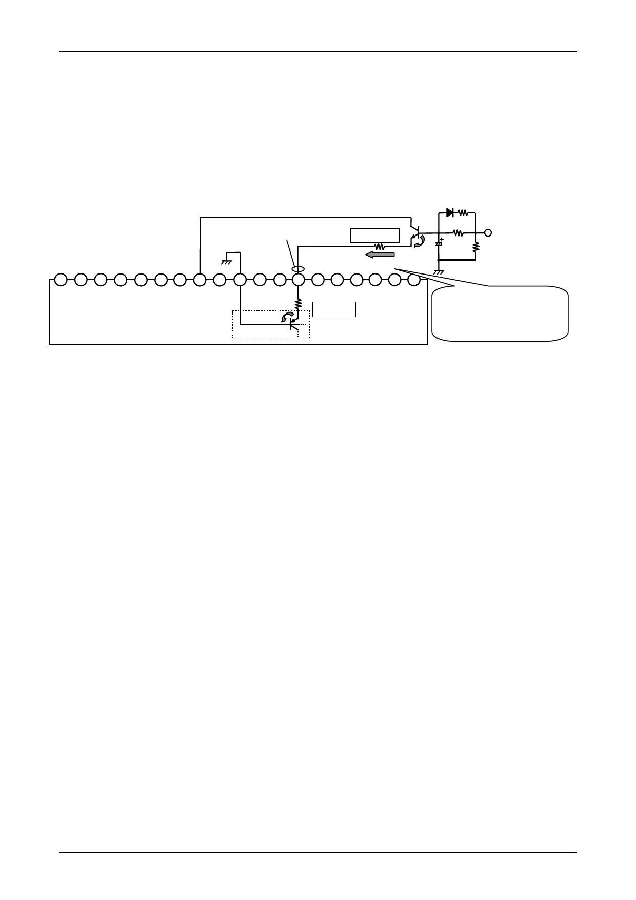
[STK433-300 series Stand-By Control Using Example]
Characteristic
• It can largely improve a pop noise to occur in power supply ON/OFF by using recommended Stand-By Control
Application.
• Because It can perform Stand-By Control by regulating limit resistance to the voltage such as used microcomputers, a
set design is easy.
(ex) STK433-300series test circuit. When impressed by Stand-by control control [+5V].
Concerning pin 13 reference
voltage VST
2.7kΩ(*1)
ΔVBE
Sink current IST
1kΩ
33kΩ
33μF
(*3)
Stand-by Control
H: Operation Mode (+5V)
L: Stand-by Mode (0V)
2kΩ
(*4)
1 2 3 4 5 6 7 8 9 10 11 12 13 14 15 16 17 18 19
-PRE -VCC +VCC Ch1 Ch1 Ch2 Ch2 +PRE SUB GND
OUT OUT OUT OUT
Ch1 Ch1 ST-
IN NF BY
Ch2 Ch2 Ch3 Ch3 Ch3 Ch3
NF
IN
IN NF OUT OUT
STK433-300 series
ΔVBE
Bias Circuit
4.7kΩ(*2)
in PreDriver IC
ex) Stand-By control voltage=+5V
VST=(5V-VBE×2)×4.7kΩ/((*1)+4.7kΩ)+VBE
=(5V-0.6V×2)×4.7kΩ/(4.7kΩ+2.7kΩ)+0.6V
≈3.0(V)
Operation Explanation
(1) Concerning pin 13 reference voltage VST
<1> Operation mode
The SW transistor of bias circuit is turned on at VST≥2.5V, and the amplifier becomes operation mode.
ex) VST=2.5V
VST=(*2)×IST+0.6V→2.5V=4.7kΩ×IST+0.6V, IST≈0.40mA
<2> Standby mode
The SW transistor of Pre-driver IC is turned off at VST≤0.6V (typ0V), and the amplifier becomes Stand-By
Mode.
ex) VST=0.6V
VST=(*2)×IST+0.6V→0.6V=4.7kΩ×IST+0.6V, IST≈0mA
(*3) It can improve a pop noise at power up time by giving a time constant of the condenser during operation.
(*4) Please decide a time constant to discharge the condenser during standby.
No. A1630-10/13
Share Link: 