ST70135 Ver la hoja de datos (PDF) - STMicroelectronics
Número de pieza
componentes Descripción
Fabricante
ST70135 Datasheet PDF : 29 Pages
| |||
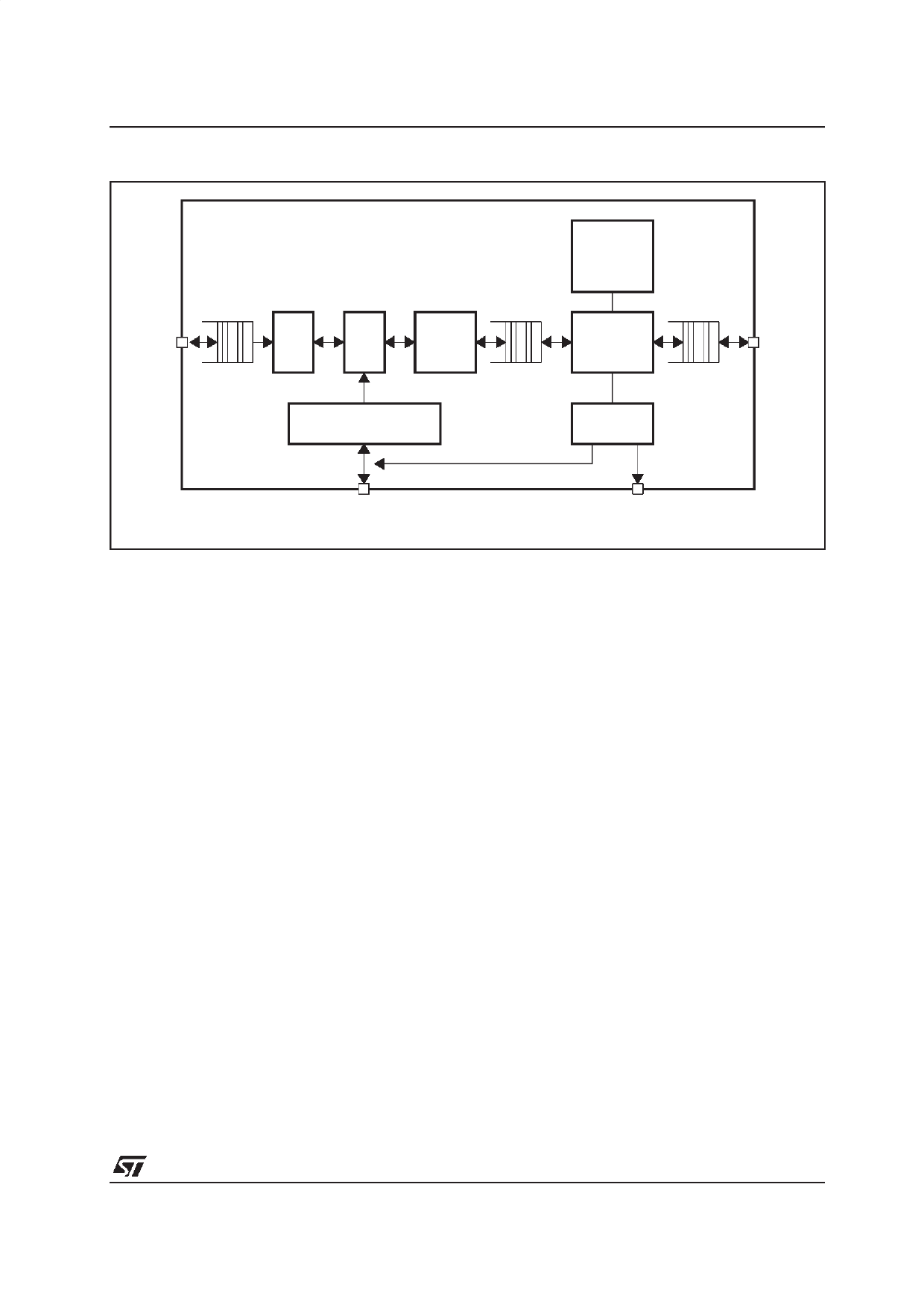
Figure 5 : DMT Modem (Rx & Tx)
To/From
DSP FE
FFT
IFFT
FEQ
FTG
ROTOR
FEQ COEFFICIENTS
ST70135A
TREILLIS
CODING
DECODING
MAPPER
DEMAPPER
MONITOR
To/From
TC
FEQ
Update
Monitor
Indications
This stream is still affected by carrier specific
channel distortion resulting in an attenuation of
the signal amplitude and a rotation of the signal
phase. To compensate, a Frequency domain
equalizer (FEQ) and a Rotor (phase shifter) are
implemented. The frequency domain equalization
performs an operation on the received vector in
order to match it with the associated point in the
constellation. The coefficient used to perform the
equalization are floating point, and may be
updated by hardware or software, using a
mechanism of active and inactive table to avoid
DMT synchro problems.In the transmit path, the
IFFT reverses the DMT symbol from frequency
domain to time domain.
The IFFT block is preceded by Fine Tune Gain
(FTG) and Rotor stages, allowing for a
compensation of the possible frequency mismatch
between the master clock frequency and the
transmitter clock frequency (which may be locked
to another reference).
The Inverse Fast Fourier Transform process is
used to transform from frequency domain to time
domain (transmit path). 256 positive frequencies
are processed, giving 512 samples in the time
domain.
The FFT module is a slave DSP engine controlled
by the firmware running on an external controller.
It works off line and communicates with other
blocks through buffers controlled by the ”Data
Symbol Timing Unit”. The DSP executes a
program stored in a RAM area, which constitutes
a flexible element that allows for future system
enhancements.
DPLL
The Digital PLL module receives a metric for the
phase error of the pilot tone. In general, the clock
frequencies at the ends (transmitter and receiver)
do not match exactly. The phase error is filtered
and integrated by a low pass filter, yielding an
estimation of the frequency offset. Various
processes can use this estimate to deal with the
frequency mismatch.
In particular, small accumulated phase error can
be compensated in the frequency domain by a
rotation of the received code constellation (Rotor).
Larger errors are compensated in the time domain
by inserting or deleting clock cycles in the sample
input sequence.
Eventually that leads to achieve less than 2ppm
between the two ends.
Mapper/Demapper, Monitor, Trellis Coding,
FEQ Update
The Demapper converts the constellation points
computed by the FFT to a block of bits. This
means to identify a point in a 2D QAM
constellation plane. The Demapper supports
Trellis coded demodulation and provides a Viterbi
maximum likelihood estimator. When the Trellis is
active, the Demapper receives an indication for
the most likely constellation subset to be used.
11/29
Share Link: 