ST70135 Ver la hoja de datos (PDF) - STMicroelectronics
Número de pieza
componentes Descripción
Fabricante
ST70135 Datasheet PDF : 29 Pages
| |||
ST70135A
I
= Input, CMOS levels
I-PU = Input with pull-up resistance, CMOS
levels
I-PD = Input with pull-down resistance,
CMOS levels
I-TTL = Input TTL levels
O
= Push-pull output
OZ = Push-pull output with high-impedance
state
IO = Input / Tristate Push-pull output
BS cell = Boundary-Scan cell
I
= Input cell
O
= Output cell
B
= Bidirectional cell
C
= Clock
Main Block Description
The following drawings describe the sequence of
functions performed by the chip.
DSP Front-End
The DSP Front-End contains 4 parts in the
receive direction: the Input Selector, the Analog
Front-End Interface, the Decimator and the Time
Equalizer. The input selector is used internally to
enable test loopbacks inside the chip. The Analog
Front-End lnterface transfers 16-bit words,
multiplexed on 4 input/output signals. Word
transfer is carried out in 4 clock cycles.
The Decimator receives 16-bit samples at 8.8MHz
(as sent by the Analog Front-End chip: ST70134)
and reduces this rate to 2.2MHz.
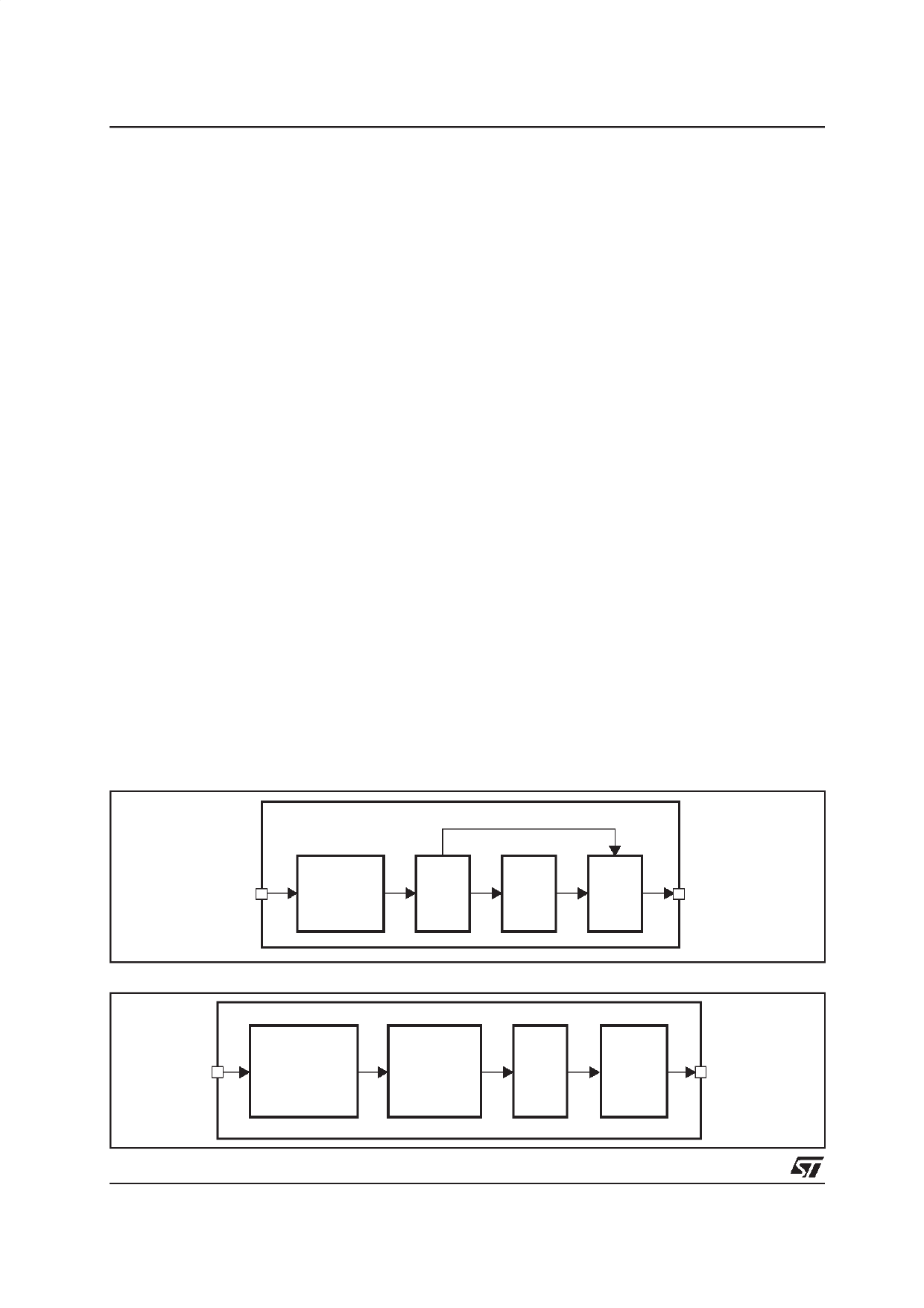
Figure 3 : DSP Front-End Receive
The Time Equalizer (TEQ) module is a FIR filter
with programmable coefficients. Its main purpose
is to reduce the effect of Inter-Symbol
Interferences (ISI) by shortening the channel
impulse response. Both the Decimator and TEQ
can be bypassed. In the transmit direction, the
DSP Front-End includes: sidelobe filtering,
clipping, delay equalization and interpolation. The
sidelobe filtering and delay equalization are
implemented by IIR Filters, reducing the effect of
echo in FDM systems. Clipping is a statistical
process limiting the amplitude of the output signal,
optimizing the dynamic range of the AFE. The
interpolator receives data at 2.2MHz and
generates samples at a rate of 8.8MHz.
DMT Modem
This module is a programmable DSP unit. Its
instruction set enables the basic functions of the
DMT algorithm like FFT, IFFT, Scaling, Rotor and
Frequency Equalization (FEQ) in compliance with
ANSI T1.413 specifications.
In the RX path, the 512-point FFT transforms the
time-domain DMT symbol into a frequency
domain representation which can be further
decoded by the subsequent demapping stages.
In other words, the Fast Fourier Transform process
is used to transform from time domain to frequency
domain (receive path). 1024 time samples are
processed. After the first stage time domain
equalization and FFT block an ICI (InterCarrier
Interference) free information stream turns out.
BYPASS
From
Analog
Front-end
IN
SELECT
AFE
I/F
DEC
TEC
To DMT
Modem
Figure 4 : DSP Front-End Transmit
From
DMT
Modem
FILTERING
CLIPPING
DELAY
EQUALIZER
INTER-
POLATOR
AFE
OUT
To Analog
I/F
SELECT
Front End
10/29
Share Link: 