SP813L Ver la hoja de datos (PDF) - Exar Corporation
Número de pieza
componentes Descripción
Fabricante
SP813L Datasheet PDF : 18 Pages
| |||
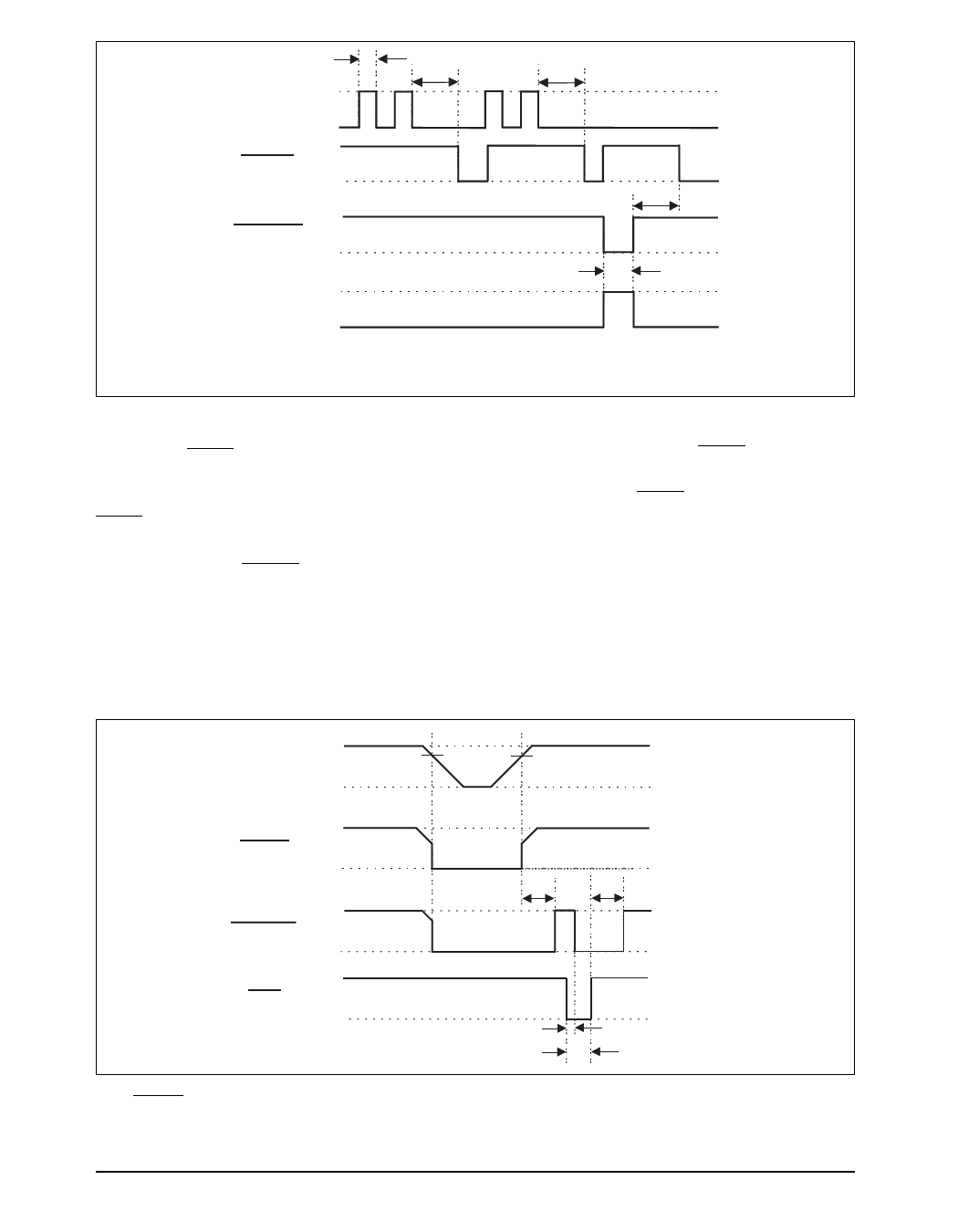
tWP
tWD
tWD
+5V
WDI 0V
+5V
WDO 0V
+5V
RESET* 0V
+5V
RESET* 0V
tWD
tRS
* externally triggered LOW by MR,
RESET is for the SP813L only
Figure 14. SP705/706/813L Watchdog Timing Waveforms
Typically, WDO will be connected to the
non-maskable interrupt input (NMI) of a µP.
When VCC drops below the reset threshold,
WDO will go LOW whether or not the watch-
dog timer has timed out. Normally this would
trigger an NMI but RESET goes LOW simulta-
neously, and thus overrides the NMI.
If WDI is left unconnected, WDO can be used as
a low-line output. Since floating WDI disables
the internal timer, WDO goes LOW only when
VCC falls below the reset threshold, thus func-
tioning as a low-line output.
+5V
VRT
VRT
VCC
0V
+5V
WDO
0V
+5V
RESET
0V
tRS
tRS
MR*
+5V
0V
*externally driven LOW
tMD
tMR
Figure 15. SP705/706 Timing Diagrams with WDI Tri-stated. The SP707/708/813L RESET Output is the Inverse
of the RESET Waveform Shown.
June 2008 Rev C
SP705 Low Power Microprocessor Supervisory Circuits
10
© 2008 Exar Corporation
Share Link: 