CS2841B Ver la hoja de datos (PDF) - Cherry semiconductor
Número de pieza
componentes Descripción
Fabricante
CS2841B Datasheet PDF : 6 Pages
| |||
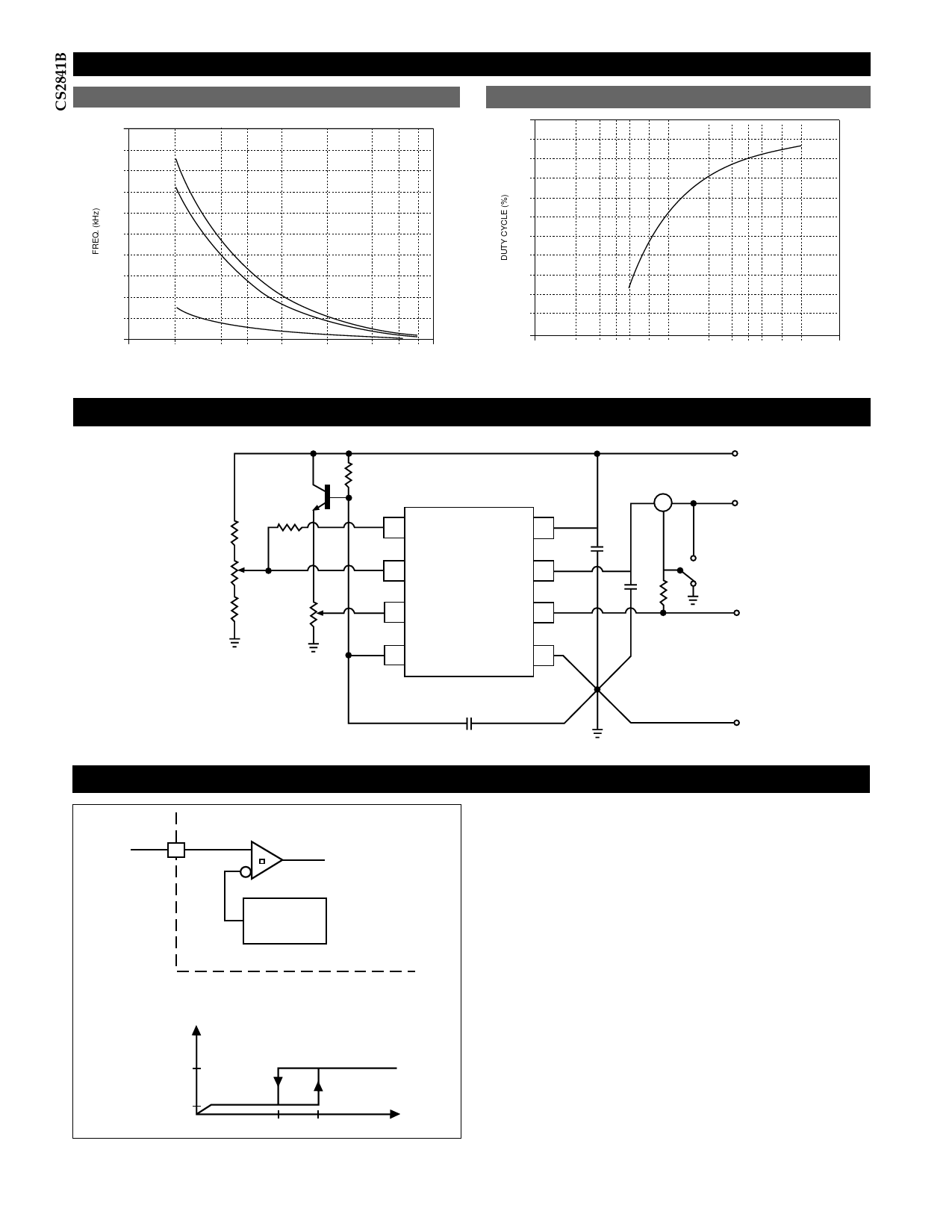
Typical Performance Characteristics:
Oscillator Frequency vs CT
Oscillator Duty Cycle vs RT
900
800
RT =680Ω
700
600
500
RT =1.5kΩ
400
300
200
RT =10kΩ
100
.0005
.001
.002 .003 .005
.01
CT (µF)
.02 .03 .04 .05
100
90
80
70
60
50
40
30
20
10
100
200 300 400 500 700 1k
2k 3k 4k 5k 7k 10k
RT (Ω)
Test Circuit
4.7kΩ
1kΩ
Error Amp
Adjust
4.7kΩ
RT
2N2222
100kΩ
COMP
5kΩ
Sense
Adjust
VFB
Sense
OSC
VREF
VCC
V O UT
Gnd
A
0.1µF
1kΩ
0.1µF
1W
VREF
VCC
VO
Gnd
CT
Circuit Description
VCC
ON/OFF Command
to reset of IC
VON = 8.0V
VOFF= 7.4V
ICC
<15mA
<1mA
7.4V 8.0V
Figure 1: Typical Undervoltage Characteristics
VCC
Undervoltage Lockout
During Undervoltage Lockout (Figure 1), the output driv-
er is biased to a high impedance state. The output should
be shunted to ground with a resistor to prevent output
leakage current from activating the power switch.
PWM Waveform
To generate the PWM waveform, the control voltage from
the error amplifier is compared to a current sense signal
which represents the peak output inductor current (Figure
2). An increase in VCC causes the inductor current slope to
increase, thus reducing the duty cycle. This is an inherent
feed-forward characteristic of current mode control, since
the control voltage does not have to change during
changes of input supply voltage.
When the power supply sees a sudden large output cur-
rent increase, the control voltage will increase allowing the
duty cycle to momentarily increase. Since the duty cycle
tends to exceed the maximum allowed to prevent trans-
4
Share Link: 