EM83702 Ver la hoja de datos (PDF) - ELAN Microelectronics
Número de pieza
componentes Descripción
Fabricante
EM83702 Datasheet PDF : 11 Pages
| |||
EM83702
ALL IN ONE MOUSE CONTROLLER
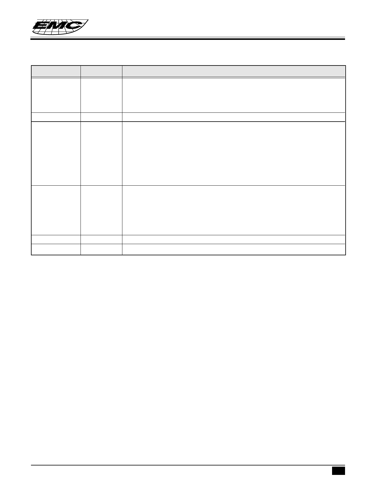
Symbol
RXD
V
SS
R
M
L
X1
X2
Y1
Y2
OPT
VDD
I/O
Function
O
There are 8 or 7 bits in each data byte.
Using parallel-in and serial-out components, the data bytes are shifted out from bit
0 through the high bits. EM83702 will transmit the data while the status of three
keyswitches or the state of the horizontal counter or vertical counter is changed.
Negative power input.
I
Three key-switches exert seven different combinations totally.
I/O
Both key-pressed and key-released signals will be sent accomplanied with
I/O
horizontal and vertical state. The status of the key-switches will be preserved,
whenever the value of horizontal or vertical counters will present at RXD. And the
debounce interval for both key-press and key-release is 13 ms.
In testing mode, L and M are the outputs of motion detecdor. Using R key can select
the two outputs X1, X2 or Y1,Y2. This feature can help manufacturer to adjust the
phase of four photo-couples for improving the yield.
I
Four photo-couple signals denote UP, DOWN, LEFT and RIGHT state. If
EM83702 is in 1200 baud rate on non-auto speed mode, the system provides 40
transmission cycles per second in microsoft mode to the utmost. In mouse system
mode, the cycles are 24 maxiun. During the scaning period, as long as the photo-
couples change their states, the value of vertical or horizontal counter will increase
or decrease accordingly.
I
Whenever OPT is connected to V , the chip will enter testing mode.
DD
Power.
FUNCTION DESCRIPTIONS
A) Operating Mode
Mouse system mode
Anytime the mouse changes its state, including the key-switches and the photo-couple sensors, EM83702 will
detect the result and transmit to RS-232C. Mouse system transmits the result with five bytes in 1200 baud
rate. Each byte contains 10 bits, one start bit, one stop bit and eight data bits. The first byte represents
the key-switches status. The second byte denote the number counted by the horizontal counter. The third byte
conveys the number accumulated by the vertical counter. If the mouse is moved faster, the photo-couple
sensors detect the “change state” and output the record, excessive horizontal counter will be transported
through the fourth byte, and vertical counter through the fifth byte. Otherwise, the fourth and fifth byte are zero.
Output bytes arrange:
bit no ...... 7 6 5 4 3 2 1
0
1st byte...... 1 0 0 0 0 L’ M’ R’*
2nd byte...... H7 H6 H5 H4 H3 H2 H1 H0
3rd byte...... V7 V6 V5 V4 V3 V2 V1 V0
4th byte...... H7 H6 H5 H4 H3 H2 H1 H0
5th byte...... V7 V6 V5 V4 V3 V2 V1 V0
* ‘ denotes complement
* This specification are subject to be changed without notice.
4.15.1996 3
Share Link: 