STK4028II(1998) Ver la hoja de datos (PDF) - SANYO -> Panasonic
Número de pieza
componentes Descripción
Fabricante
STK4028II
(Rev.:1998)
(Rev.:1998)
SANYO -> Panasonic

STK4028II Datasheet PDF : 4 Pages
| |||
Ordering number : EN4548A
Thick Film Hybrid IC
STK4028 II
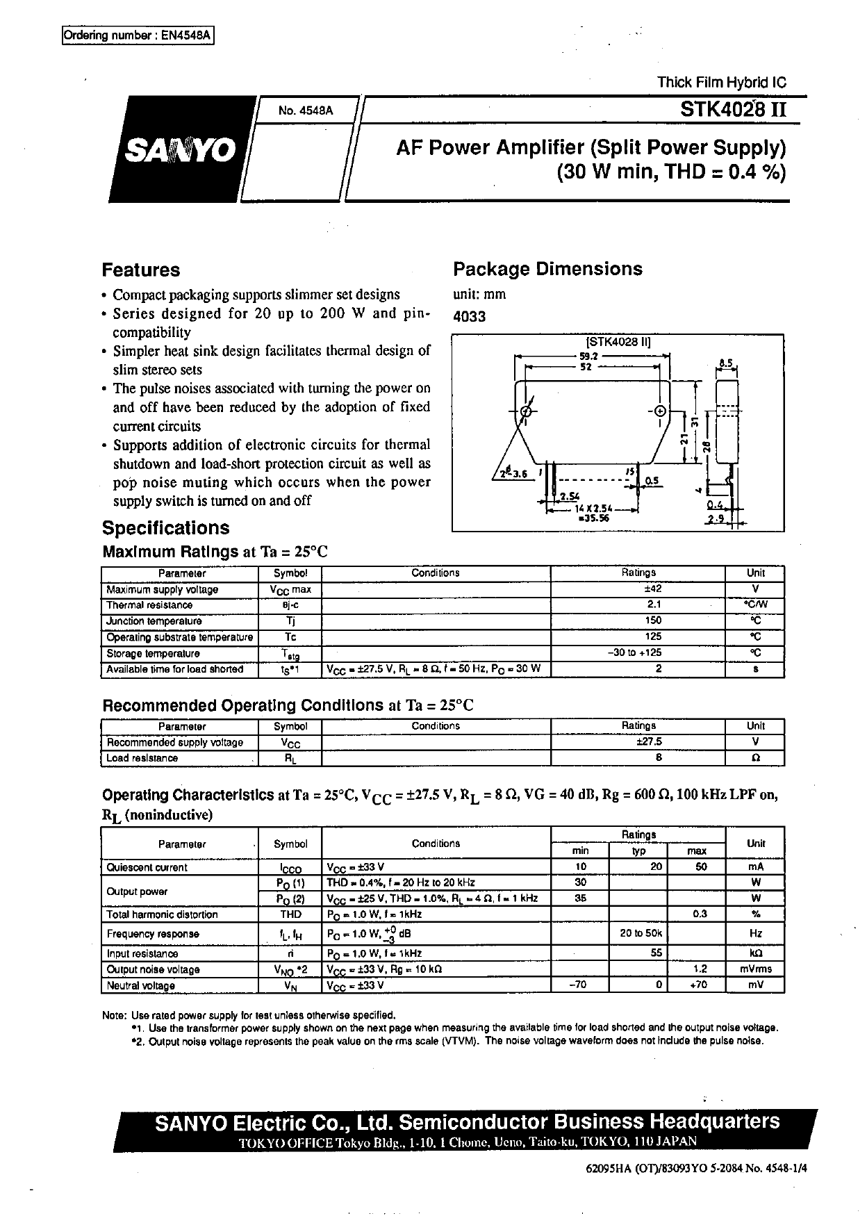
AF Power Amplifier (Split Power Supply)
(30 W min, THD = 0.4 %)
Features
• Compact packaging supports slimmer set designs
• Series designed for 20 up to 200 W and pin-
compatibility
• Simpler heat sink design facilitates thermal design of
slim stereo sets
• The pulse noises associated with turning the power on
and off have been reduced by the adoption of fixed
current circuits
• Supports addition of electronic circuits for thermal
shutdown and load-short protection circuit as well as
pop noise muting which occurs when the power
supply switch is turned on and off
Specifications
Maximum Ratings at Ta = 25°C
Parameter
Maximum supply voltage
Thermal resistance
Junction temperature
Operating substrate temperature
Storage temperature
Available time for load shorted
Symbol
VCC max
θj-c
Tj
Tc
Tstg
tS*1
Conditions
VCC = ±27.5 V, RL = 8 Ω, f = 50 Hz, PO = 30 W
Ratings
±42
2.1
150
125
–30 to +125
2
Unit
V
°C/W
°C
°C
°C
s
Recommended Operating Conditions at Ta = 25°C
Parameter
Recommended supply voltage
Load resistance
Symbol
VCC
RL
Conditions
Ratings
Unit
±27.5
V
8
Ω
Operating Characteristics at Ta = 25°C, VCC = ±27.5 V, RL = 8 Ω, VG = 40 dB, Rg = 600 Ω, 100 kHz LPF on,
RL (noninductive)
Parameter
Symbol
Conditions
Ratings
Unit
min
typ
max
Quiescent current
Output power
Total harmonic distortion
Frequency response
Input resistance
Output noise voltage
Neutral voltage
ICCO
VCC = ±33 V
10
PO (1) THD = 0.4%, f = 20 Hz to 20 kHz
30
PO (2) VCC = ±25 V, THD = 1.0%, RL = 4 Ω, f = 1 kHz
35
THD
PO = 1.0 W, f = 1kHz
fL, fH
PO
=
1.0
W,
+0
–3
dB
ri
PO = 1.0 W, f = 1kHz
VNO *2 VCC = ±33 V, Rg = 10 kΩ
VN
VCC = ±33 V
–70
20
50
0.3
20 to 50k
55
1.2
0
+70
mA
W
W
%
Hz
kΩ
mVrms
mV
Note: Use rated power supply for test unless otherwise specified.
*1. Use the transformer power supply shown on the next page when measuring the available time for load shorted and the output noise voltage.
*2. Output noise voltage represents the peak value on the rms scale (VTVM). The noise voltage waveform does not include the pulse noise.
Any and all SANYO products described or contained herein do not have specifications that can handle
applications that require extremely high levels of reliability, such as life-support systems, aircraft’s
control systems, or other applications whose failure can be reasonably expected to result in serious
physical and/or material damage. Consult with your SANYO representative nearest you before using
any SANYO products described or contained herein in such applications.
SANYO assumes no responsibility for equipment failures that result from using products at values that
exceed, even momentarily, rated values (such as maximum ratings, operating condition ranges, or other
parameters) listed in products specifications of any and all SANYO products described or contained
herein.
SANYO Electric Co.,Ltd. Semiconductor Bussiness Headquarters
TOKYO OFFICE Tokyo Bldg., 1-10, 1 Chome, Ueno, Taito-ku, TOKYO, 110-8534 JAPAN
O3098HA (OT)/62095HA (OT)/83093YO 5-2084 No. 4548-1/4
Share Link: