DS2405 Ver la hoja de datos (PDF) - Dallas Semiconductor -> Maxim Integrated
Número de pieza
componentes Descripción
Fabricante
DS2405 Datasheet PDF : 15 Pages
| |||
DS2405
Hardware Configuration
The 1-Wire bus has only a single line by definition; it is important that each device on the bus be able to
drive it at the appropriate time. To facilitate this, each device attached to the 1-Wire bus must have an
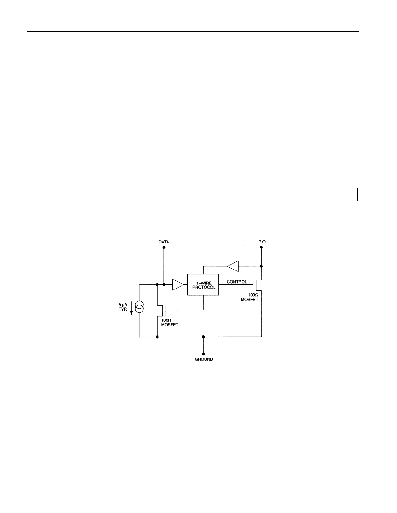
open drain connection or 3-state outputs. The DS2405 is an open drain part with an internal circuit
equivalent to that shown in Figure 2. The bus master can be the same equivalent circuit. If a bidirectional
pin is not available, separate output and input pins can be tied together. The bus master requires a pullup
resistor at the master end of the bus, with the bus master circuit equivalent to the one shown in Figure 3.
The value of the pullup resistor should be approximately 5 kΩ for short line lengths. A multidrop bus
consists of a 1-Wire bus with multiple slaves attached. The 1-Wire bus has a maximum data rate of
16.3kbits/s.
The idle state for the 1-Wire bus is high. If, for any reason, a transaction needs to be suspended, the bus
MUST be left in the idle state if the transaction is to resume. If this does not occur and the bus is left low
for more than 120 μs, one or more of the devices on the bus may be reset. In addition, the state of the PIO
pin for one or more of the DS2405s on the bus may return to its default (off) condition.
DS2405 MEMORY MAP Figure 1
8-Bit CRC Code
48-Bit Serial Number
MSB
LSB MSB
LSB
8-Bit Family Code (05h)
MSB
LSB
DS2405 EQUIVALENT CIRCUIT Figure 2
3 of 15
Share Link: 