SLA7024M Ver la hoja de datos (PDF) - Allegro MicroSystems
Número de pieza
componentes Descripción
Fabricante
SLA7024M Datasheet PDF : 12 Pages
| |||
SLA7024M, SLA7026M, AND SMA7029M
HIGH-CURRENT PWM,
UNIPOLAR STEPPER MOTOR
CONTROLLER/DRIVERS
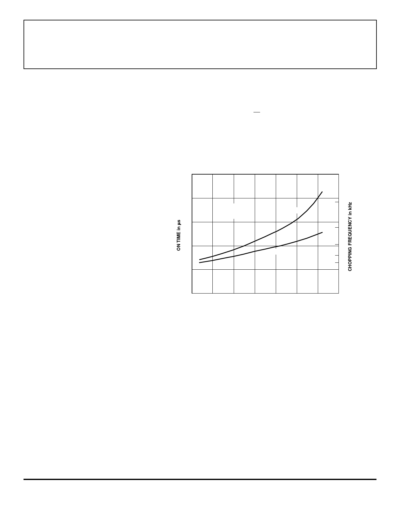
DETERMINING THE MOTOR PWM FREQUENCY
The modules function asynchronously, with PWM OFF time fixed by R3
and
C1
at input td.
tOFF ≈ -R3
The
• C1
OFF time
• logn (1 -
can
V2 b)
be
calculated
as:
(5)
Recommended circuit constants and tOFF are:
Vb = 5 V
R3 = 47 kΩ
C1 = 470 pF
tOFF = 12 µs
50
40
20
RS = 1 Ω
L/R = 1 to 3 ms
VCC = 24 V
30
25
20
30
VCC = 36 V
35
40
10
0
0
2
4
6
8
10
12
14
MOTOR RESISTANCE in OHMS
Dwg. GK-016
FIGURE 7.
PWM FREQUENCY vs MOTOR RESISTANCE
POWER DISSIPATION CALCULATIONS
Excepting high-current applications utilizing the SLA7026M above
approximately 2.0 A at +65°C (with 2-phase operation), the need for heat
sinks is rare. The basic constituents of conduction losses (internal power
dissipation) include:
(a) FET output power dissipation (IOUT2 • rDS(on) or IOUT • VDS(ON)),
(b) FET body diode power dissipation (VSD • IOUT), and
(c) control circuit power dissipation (VCC • ICC).
Device conduction losses are calculated based on the operating mode
(wave drive, half-step, or 2-phase). Assuming a 50% output duty cycle:
Wave Drive = 0.5 (IOUT2 • rDS(on)) + 0.5 (VSD • IOUT) + (VCC • 15 mA)
Half-Step = 0.75 (IOUT2 • rDS(on)) + 0.75 (VSD • IOUT) + (VCC • 15 mA)
2-Phase = (IOUT2 • rDS(on)) + (VSD • IOUT) + (VCC • 15 mA)
Share Link: 