IXCY01N90E Ver la hoja de datos (PDF) - IXYS CORPORATION
Número de pieza
componentes Descripción
Fabricante
IXCY01N90E Datasheet PDF : 3 Pages
| |||
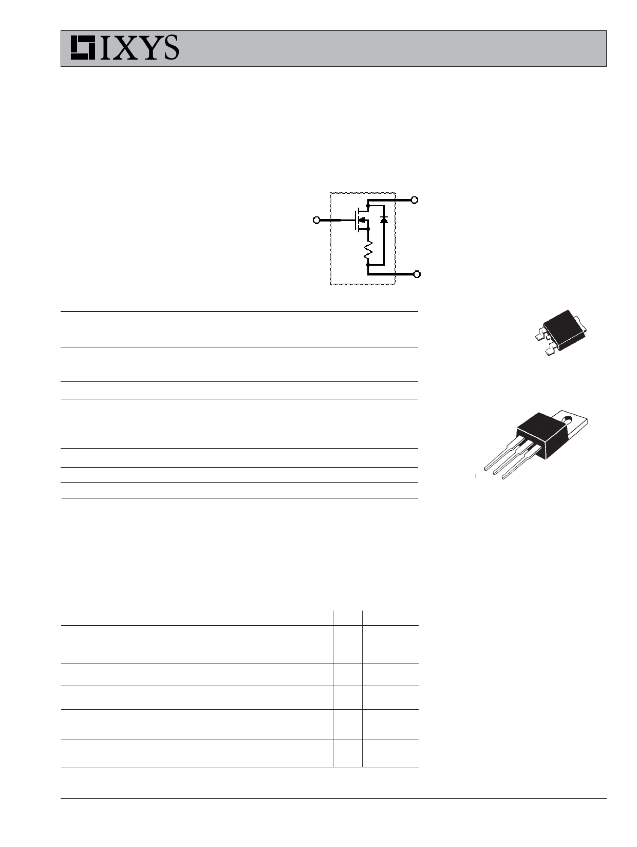
Gate Controlled
Current Limiter
N-Channel, Enhancement Mode
IXCP 01N90E
IXCY 01N90E
V=
I DSS =
D(limit)
R=
DS(on)
900 V
250mA
80 Ω
D
G
S
Symbol
Test Conditions
Maximum Ratings TO-252 (IXCY)
VDSS
VDGR
TJ = 25°C to 150°C
TJ = 25°C to 150°C; RGS = 1 MΩ
900
V
900
V
G
TAB
VGS
VGSM
Continuous
Transient
±20
V
S
±30
V
PD
TC = 25°C
TJ
TJM
Tstg
40
-55 ... +150
W
°C
TO-220 (IXCP)
150
°C
-55 ... +150
°C
TAB
TL
1.6 mm (0.062 in.) from case for 10 s
300
°C
Md
Weight
Mounting torque with 3.5mm screw (TO-220)
0.55/5 Nm/lb.in.
TO-251/252 = 1 g, TO-220 = 4 g
G DS
G = Gate,
S = Source,
D = Drain,
TAB = Drain
Symbol
VDSS
VGS(th)
IGSS
IDSS
RDS(on)
IDP
Test Conditions
Characteristic Values
(TJ = 25°C, unless otherwise specified)
min. typ. max.
VGS = 0 V, ID = 25 µA
900
VDS = VGS, ID = 25 µA
2.5
VGS = ±20 V, VDS = 0
VDS = VDSS; VGS = 0 V
VGS = 10 V, ID = 50 mA
Pulse test, t ≤ 300 µs, duty cycle d ≤ 2 %
Plateau Current; VDS = 10 V, VGS = 10V
100
Pulse test, t ≤ 300 µs, duty cycle d ≤ 2 %
V
5V
±50 nA
10 µA
80 Ω
130 mA
Features
• High output resistance in the saturated
mode of operation
• Rugged HDMOSTM process
• Stable peak drain current limit
• High voltage current regulator
• International standard packages
Applications
• Current regulation
• Over current and over voltage
• protection for sensitive loads
Linear regulator
© 2002 IXYS All rights reserved
98701-A (8/02)
Share Link: 