MRFIC0904 Ver la hoja de datos (PDF) - Motorola => Freescale
Número de pieza
componentes Descripción
Fabricante
MRFIC0904 Datasheet PDF : 8 Pages
| |||
RECOMMENDED OPERATING RANGES (TA = 25°C unless otherwise noted)
Parameter
Symbol
Supply Voltage
VDD
VSS
Bias Voltage Range
BIAS
Power Control Voltage Range
PCNTRL
Enable Voltage ON State
ENABLE
Enable Voltage OFF State
ENABLE
RF Frequency
f
Value
2.7 to 5.0
– 2.75 to – 2.25
0 to 1.0
0 to 3.0
2.5
0.5
800 to 1000
Unit
Vdc
Vdc
Vdc
Vdc
Vdc
MHz
W ELECTRICAL CHARACTERISTICS (VDD = 3.6 V, VSS = –2.5 V, BIAS = 0.0 V, PCNTRL = 3.0 V, ENABLE = 3.0 V, Pin = –2 dBm,
f = 900 MHz, ZO = 50 , TA = 25°C unless otherwise noted)
Characteristic
Min
Typ
Max
Unit
Supply Current
IDD
ISS
Standby Current: Off–mode (ENABLE = 0 V)
IDD
ISS
Output Power
mA
—
120
160
—
1.0
1.75
µA
—
50
130
—
60
360
22.5
24
—
dBm
Output Power at 1 dB Gain Compression
—
24.5
—
dBm
Input Return Loss
—
14
—
dB
PCNTRL Current
—
200
—
µA
ENABLE Current
—
200
—
µA
Gain Control Range
—
45
—
dB
Enable/Control Input 3 dB Bandwidth
—
1
—
MHz
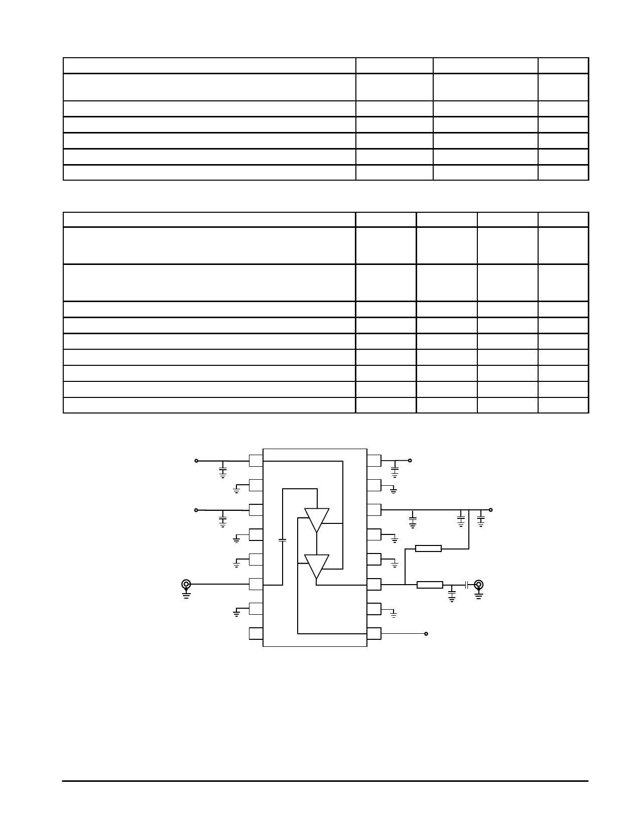
(1) All electrical Characteristics are measured in test circuit schematic as shown in Figure 1.
PCNTRL
1
C6
2
VSS
3
C7
4
5
RF IN
6
7
8
16
ENABLE
C5
15
14
C8
13
12
11
10
C4
T1
C3 VDD
T2
C2
RF OUT
C1
9
BIAS
C1 – 2.7 pF
C2, C4, C8 – 100 pF
C3 – 1 µF
C5, C6 – 10 pF
C7 – 1000 pF
T1 – 90° @ 900 MHz, Z0 = 100 Ω
T2 – 9° @ 900 MHz, Z0 = 50 Ω
BOARD MATERIAL = FR4
Figure 1. Applications Circuit Configuration
MRFIC0904
2
MOTOROLA RF DEVICE DATA
Share Link: 