AD6190ARSRL Ver la hoja de datos (PDF) - Analog Devices
Número de pieza
componentes Descripción
Fabricante
AD6190ARSRL Datasheet PDF : 8 Pages
| |||
AD6190
PIN FUNCTION DESCRIPTIONS
No.
Pin Name
Type
Function/Description
1
PREOUT
Output
Prescaler Output. Usually connected to input of external low frequency
CMOS synthesizer (Fujitsu MB87006A, Siemens PMB2307, or similar).
2
VCOON
Control
Logic “1” turns on power to VCO, and divider/prescalers.
3
VBATT
Power
VBATT connection for regulator. Normally connected to 3.3 V dc or battery.
4
VBASE
Power
Base connection to external regulator pass transistor (MMBT3906 or similar).
5
TANK–
Input
Connection for VCO tank circuit (LC network).
6
GND
Power
Substrate ground connection.
7
TANK+
Input
Connection for VCO tank circuit (LC network).
8
RSSI
Output
Received Signal Strength Indicator output signal.
9
TXIF
Input
Accepts modulated transmit signal at 10.7 MHz IF.
10
11
12
13
14
15
16
17
18
19
20
21
22
23
24
25
26
27
28
VREG
RXON
LIMIN
IFAMPCOM
IFAMPOUT
E IFAMPIN
VCCIF
RXMIXOUT
T LNAGND
GND
RFIN
E VCCLNA
GND
LIMOUT
L PAGND
RFOUT
VCCTX
TXON
PREMOD
Power
Control
Input
Input
Output
Input
Power
Output
Power
Power
Input
Power
Power
Output
Power
Output
Power
Control
Input
Regulated VCC for LO from external pass transistor.
Logic “1” turns on power to LNA and receive mixer stages.
Input to limiting amplifier.
Input signal common for limiting amplifier.
Output of first stage of IF amplifier. Normally connected through 10.7 MHz
filter to Pin 12 (LIMIN).
Input to first stage of IF amplifier.
Local VCC connection for IF amp/limiter stages.
10.7 MHz IF Output. Normally connected through 10.7 MHz filter to IF
amplifier input (Pin 15).
Local ground for LNA.
Substrate ground connection.
LNA Input. Normally driven single-ended from 50 Ω source impedance.
VCC for LNA.
Substrate ground connection.
10.7 MHz limiter output.
Local ground for PA stage emitter. Degeneration may be added.
Transmitted RF output signal at 0 dBm level.
Local VCC connection for TX stages.
Logic “1” turns on power to transmit mixer, buffers, and PA stages.
Prescaler Modulus control (HIGH = divide-by-64; LOW = divide-by-65).
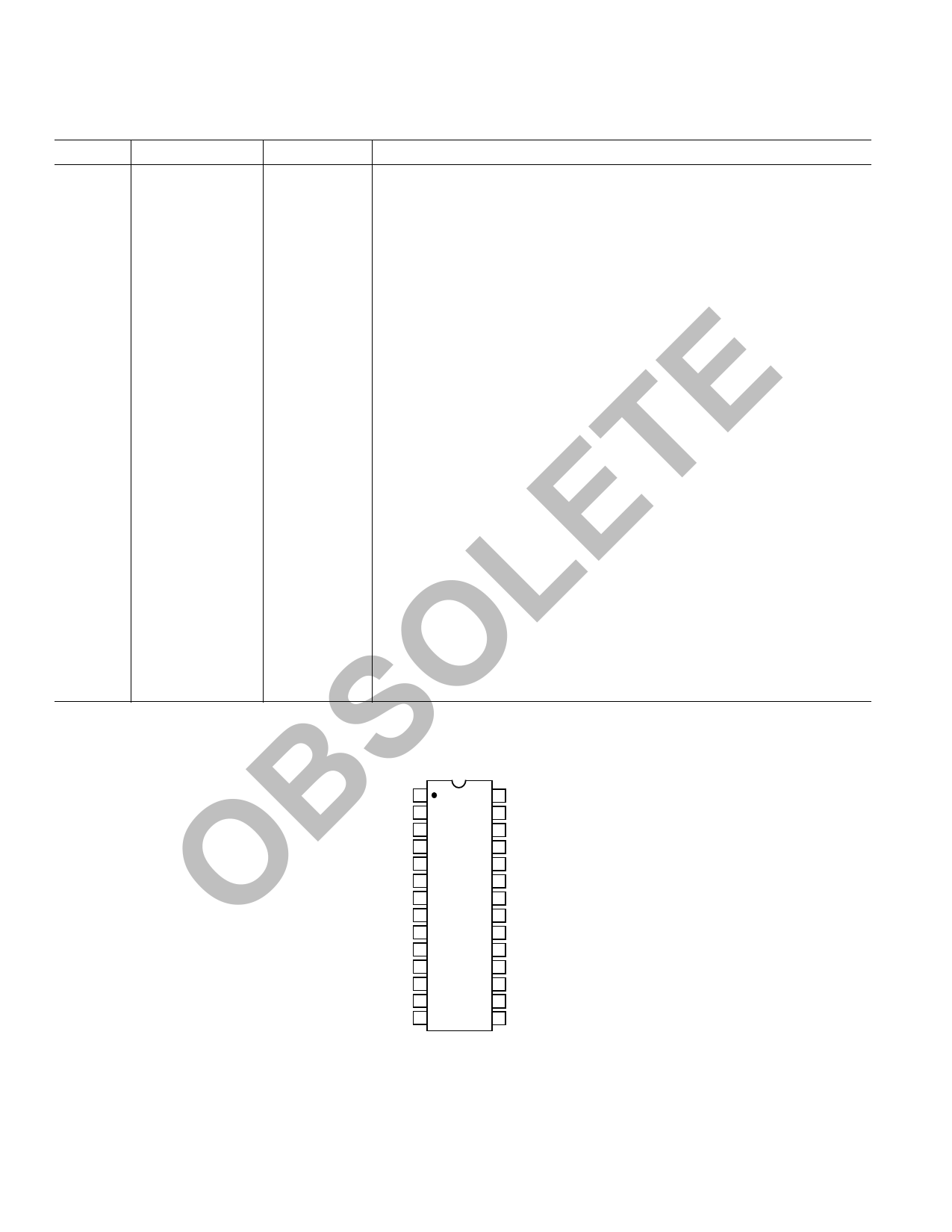
O PIN CONFIGURATION
SPREOUT 1
28 PREMOD
VCOON 2
27 TXON
VBATT 3
26 VCCTX
BVBASE 4
25 RFOUT
TANK؊ 5
24 PAGND
GND
TANK+
O RSSI
6
23
AD6190
7 TOP VIEW 22
8 (Not to Scale) 21
LIMOUT
GND
VCCLNA
TXIF 9
20 RFIN
VREG 10
19 LNAGND
RXON 11
18 LNAGND
LIMIN 12
17 RXMIXOUT
IFAMPCOM 13
16 VCCIF
IFAMPOUT 14
15 IFAMPIN
–4–
REV. 0
Share Link: 