HV300 Ver la hoja de datos (PDF) - Supertex Inc
Número de pieza
componentes Descripción
Fabricante
HV300 Datasheet PDF : 6 Pages
| |||
HV300/HV310
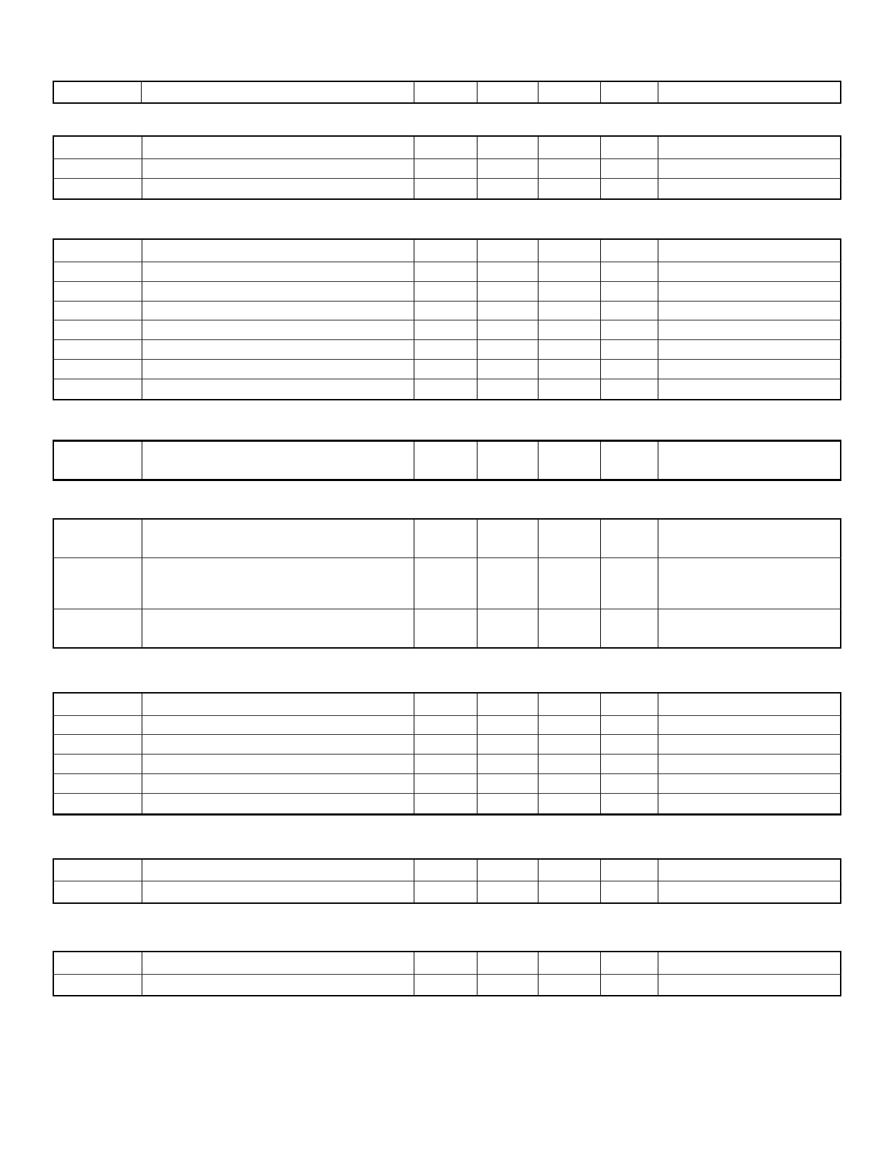
Electrical Characteristics (VIN=-10V to -90V, -40°C ≤ TA ≤ +85°C unless otherwise noted)
Symbol
Parameters
Min
Typ
Max
Unit
Conditions
Supply (Referenced to VDD pin)
VEE
Supply Voltage
IEE
Supply Current
IEE
Standby Mode Supply Current
-90
-10
V
550
650
330
400
µA VEE = -48V, Mode = Limiting
µA VEE = -48V, Mode = Standby
OV and UV Control (Referenced to VEE pin)
VUVH
UV High Threshold
VUVL
UV Low Threshold
VUVHY
UV Hysteresis
IUV
UV Input Current
VOVH
OV High Threshold
VOVL
OV Low Threshold
VOVHY
OV Hysteresis
IOV
OV Input Current
1.26
1.16
100
1.0
1.26
1.16
100
1.0
V Low to High Transition
V High to Low Transition
mV
nA VUV = VEE + 1.9V
V Low to High Transition
V High to Low Transition
mV
nA VOV = VEE + 0.5V
Current Limit (Referenced to VEE pin)
VSENSE
Current Limit Threshold Voltage
40
50
60
mV VUV = VEE + 1.9V,
VOV = VEE + 0.5V
Gate Drive Output (Referenced to VEE pin)
VGATE
Maximum Gate Drive Voltage
IGATEUP
Gate Drive Pull-Up Current
IGATEDOWN Gate Drive Pull-Down Current
9.0
10
11
V VUV = VEE + 1.9V,
VOV = VEE + 0.5V
500
µA VUV = VEE + 1.9V,
VOV = VEE + 0.5V,
40
mA VUV = VEE, VOV = VEE + 0.5V
Timing Control – Test Conditions: C =100µF, CRAMP=10nF, VUV = VEE+1.9V, VOV= VEE+0.5V, External MOSFET is IRF530*
IRAMP
Ramp Pin Output Current
10
µA VSENSE = 0V
tPOR
Time from UV to Gate Turn On
2.0
ms (Note 1)
tRISE
Time from Gate Turn On to VSENSE Limit
400
µs
tLIMIT
Duration of Current Limit Mode
5.0
ms
tPWRGD
Time from Current Limit to PWRGD
5.0
ms
VRAMP
Voltage on Ramp Pin in Current Limit Mode
3.6
V (Note 2)
Power Good Output (Referenced to VEE pin)
VPWRGD
Power Good Pin Breakdown Voltage
VPWRGD
Power Good Pin Output Low Voltage
90
V
0.5
0.8
V
IPWRGD = 1mA
Dynamic Characterstics
tGATEHLOV
tGATEHLUV
OV Delay
UV Delay
500
ns
500
ns
Note 1: This timing depends on the threshold voltage of the external N-Channel MOSFET. The higher its threshold is, the longer this timing.
Note 2: This voltage depends on the characteristics of the external N-Channel MOSFET. VGS(th) = 3V for an IRF530.
*IRF530 is a registered trademark of International Rectifier.
2
Share Link: 