BA12003B Ver la hoja de datos (PDF) - ROHM Semiconductor
Número de pieza
componentes Descripción
Fabricante
BA12003B Datasheet PDF : 7 Pages
| |||
Standard ICs
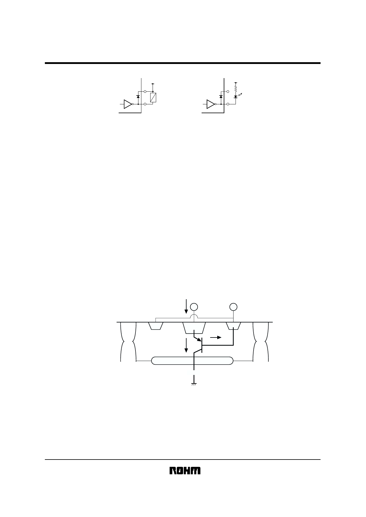
!Application example
BA12001B / BA12003B / BA12003BF / BA12004B
RY
LED
(1) Relay driver
Fig.5
(2) LED driver
!Application notes
The BA12001B is a transistor array which can be directly coupled to a general logic circuit such as PMOS, CMOS, or
TTL.
A current limiting resistor needs to be connected in series with the input.
The BA12003B / BF can be coupled directly to TTL or CMOS output (when operating at 5V). In order to limit the input
current to a stable value, resistors are connected in series to each of the inputs.
The BA12004B is designed for direct coupling to CMOS or PMOS output using a 6 to 15V power supply voltage. In order
to limit the input current to a stable value, resistors are connected in series to each of the inputs.
The load for each of these products should be connected between the driver output and the power supply. To protect the
IC from excessive swing voltage, the COM pin (Pin 9) should be connected to the power supply.
Fig.6 shows the configuration of the on-chip diode for surge absorption.
In the construction of the surge-absorbing diode,there is an N-P junction between the N-layer (N-well + BL) and the
substrate (P-sub) so that when the diode is on, current flows from the output pin to the substrate. In terms of the vertical
construction, this diode is configured similar to a PNP transistor. When using the surge-absorbing diode, take appropriate
measures regarding the thermal characteristics of the design considering the current that will be handled.
Also, if motor back-rush current or other conditions that will result continued surge current to flow to the surge-absorbing
diode can be foreseen, we strongly recommend connecting a Schottky barrier diode (or other type of diode with a low
foward voltage) in parallel with the surge-absorbing diode to construct a bypass route for the surge current.
OUT
In-flow current to the surge-absorbing diode
COM
N+
P+
N+
IDi
ISO
ISO
Isub
P
B/L
N-well
N+
P
P-sub
Fig.6 Vertical construction of the surge-absorbing diode
Share Link: 