SC4612 Ver la hoja de datos (PDF) - Semtech Corporation
Número de pieza
componentes Descripción
Fabricante
SC4612 Datasheet PDF : 24 Pages
| |||
POWER MANAGEMENT
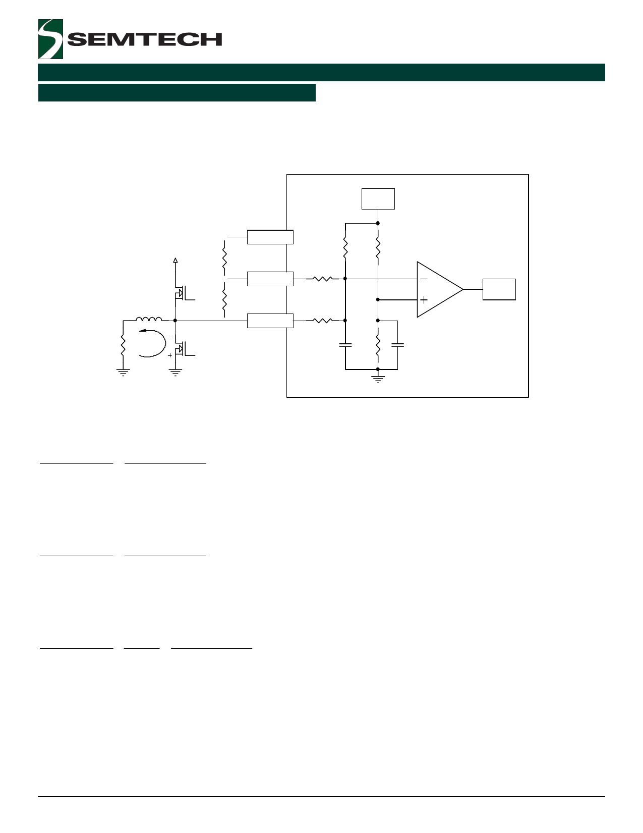
Applications Information (Cont.)
Below are examples of calculating the OCP trip voltages.
Low Side RDS_ON Current Limit
SC4612
2.75V
SC4612
Vin
Ra
DRV pin
ILIM pin
R3 R4
130k 260k
R1
2k
COMP
Rb
L
R2
+100mV
10k
PHASE pin
R Iload@Toff
load
C1
R5
C2
2pF
1 0k
5pF
OCP
1. Ra, Rb - Not installed:
2.75V − 100mV
R3
=
100mV − Vphase
R2
solving for: VPHASE = -100mV, therefore the circuit will trip @ RDS_ON x ILOAD = 100mV
2. To lower trip voltage - install Rb. For example: Rb = 13k
2.75V − 100mV
R3
=
100mV − Vphase
R2 || (Rb + R1)
solving for: VPHASE = -20mV, obviously more sensitive! RDS_ON x ILOAD = 20mV
3. To increase trip voltage - install Ra. For example: Ra = 800k; VDRIVE = 7.8V typ.
2.75V − 100mV
R3
+
Vdrive
Ra + R1
=
100mV − Vphase
R2
solving for: VPHASE = -200mV. Current limit has doubled compared to original conditions.
NOTE! Allow for tempco and RDS_ON variation of the MOSFET - see “overcurrent protection” information on page 11 in the
datasheet.
2007 Semtech Corp.
11
www.semtech.com
Share Link: 