SA9607M Ver la hoja de datos (PDF) - South African Micro Electronic Systems
Número de pieza
componentes Descripción
Fabricante
SA9607M
South African Micro Electronic Systems

SA9607M Datasheet PDF : 10 Pages
| |||
SA9607M
INPUT SIGNALS
VREF
The VREF pin is the reference for the bias resistor and is the
recommended point for calibration. With a bias resistor of
24kΩ optimum conditions are set. It may be varied within
±10% for calibration purposes. Any changes to the bias
resistor will affect the output pulse rate quadratically (i.e.(R
= +5%,(f=10%).
Motor pulse rate select (MP1 and MP0)
The pulse rate of the motor driver ouput of the SA9607M is
selected by the inputs MP1 and MP0. Three pulse rate options
are available as shown in the following table:
Pulse rate selection
Pulse Rate Selection Motor drive
Input
output
Unit
MP1
MP0
selection
VSS
VSS
1
pulses/kWh
V
SS
V
DD
10
pulses/kWh
VDD
VSS
100
pulses/kWh
VDD
VDD Device test mode
Please note that the device will not perform metering functions
as described in this document while in test mode.
Rated condition select (RATED)
The rated condition select pin gives the option of having a
3:2:1 scaling ratio of the rated current easily available. This
feature is particularly useful in circumstances where a
manufacturer requires a meter for use in a system rated for
two different conditions, for example 230V/60A and 230V/
40A. With the rated condition select the SA9607M allows for
the development of different rated meters requiring minimal
changes. The following table below lists the options available
(assuming the rated condition to be 230V/60A).
Rated condition select (RATED)
Signal Input RATED
VSS
OPEN
VDD
Rated Conditions
230V / 20A
230V / 40A
230V / 60A
OUTPUT SIGNALS
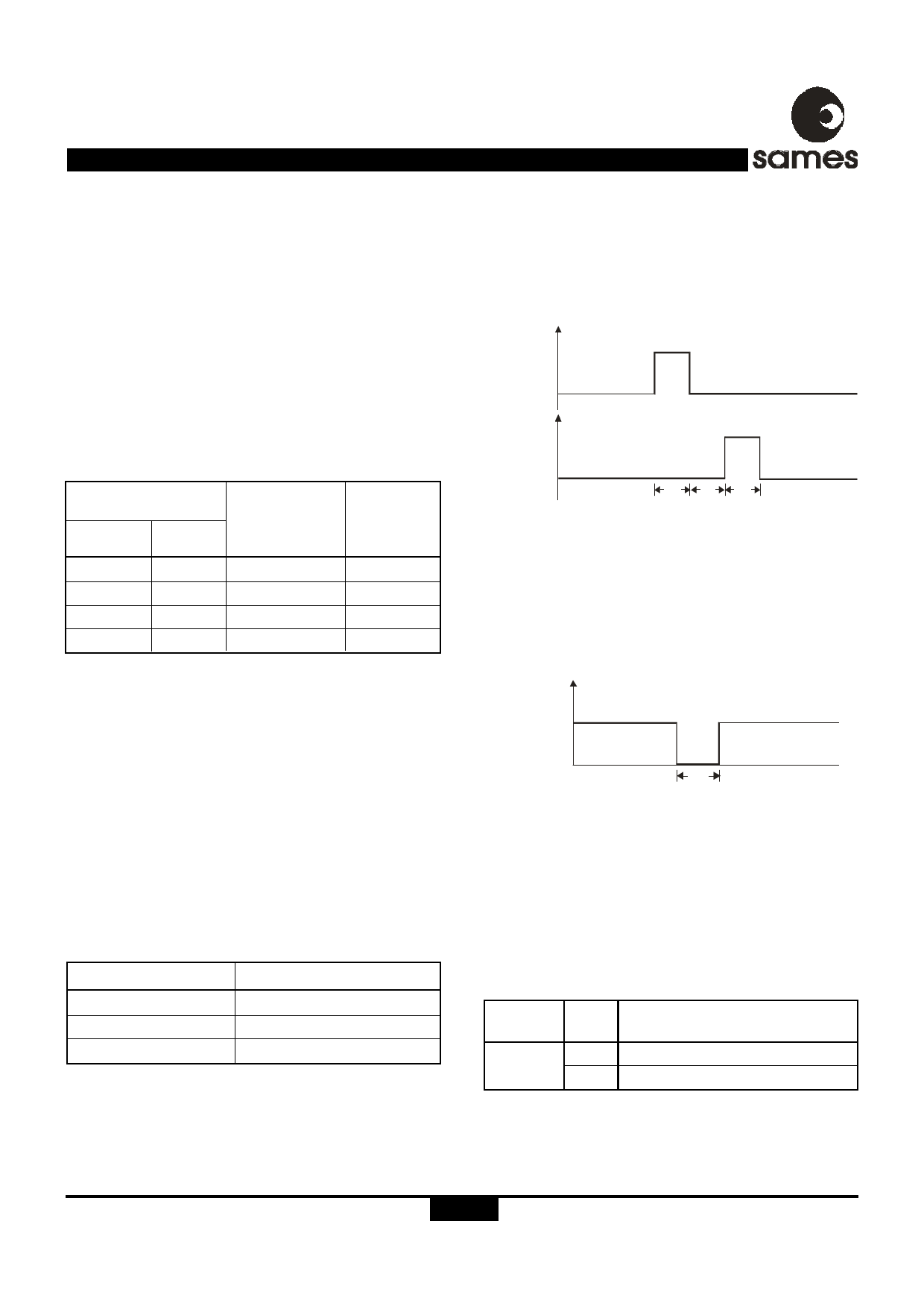
Motor output (MOP, MON)
The MON pulse will follow the MOP pulse within 142ms. This
prevents that the motor armature is in the wrong position after
a power failure. Both MOP and MON outputs are active high.
The motor drive wave forms are shown below:
VDD
MOP
VSS
MON
VDD
VSS
D R -01 559
tm
tm
tm
tm = 142ms
Figure 5: Motor drive waveform
LED output (LED)
The LED output pulse at a fixed rate of 6400 pulses per kWh.
The LED output is active low. The LED waveform is shown
below:
VDD
LED
VSS
DR-01332
tLED
tLED = 10ms
Figure 4: LED pulse output
Selected input indication (SEL1)
The SA9607M continuously compares the power consumptions
on current channel 1 inputs and current channel 2 inputs. The
larger of the two measurements are used for metering. The
SEL1 output pin indicates which channel is currently being
used for the pulse output.
Signal
Output
SEL1
Value Description
0 Channel 1selected (IIN1/IIP1)
1 Channel 2selected (IIN2/IIP2)
http://www.sames.co.za.
5/10
Share Link: