SA9024 Ver la hoja de datos (PDF) - Philips Electronics
Número de pieza
componentes Descripción
Fabricante
SA9024 Datasheet PDF : 23 Pages
| |||
Philips Semiconductors
900 MHz transmit modulator and 1.3 GHz
fractional–N synthesizer
Objective specification
SA9024
Functional Description Main Channel Synthesizer
& Auxiliary Synthesizer
CLOCK
DATA
STROBE
PD1
INM1
INM2
PD1 + PD2
INR
PD2
INA
SERIAL INPUT + PROGRAM LATCHES
FB
1
NMAIN
16
MAIN DIVIDERS
FMOD
NF
FB
3
FRACTIONAL
ACCUMULATOR
PD1
NR
12
SM
2
REFERENCE DIVIDER
MAIN
PHASE
2
DETECTOR
MAIN
REFERENCE
SELECT
÷2 ÷2 ÷2
SA
2
PD2
NAUX
14
AUXILIARY
REFERENCE
SELECT
AUXILIARY
PHASE
DETECTOR
AUXILIARY DIVIDER
FDAC
8
FDAC
8
FDAC
8
NORMAL
OUTPUT
CHARGE
PUMP
SPEED-UP
OUTPUT
CHARGE
PUMP
INTEGRAL
OUTPUT
CHARGE
PUMP
AUXILIARY
OUTPUT
2
CHARGE
PUMP
RN
PHP
PHI
RN
PHA
LOCK
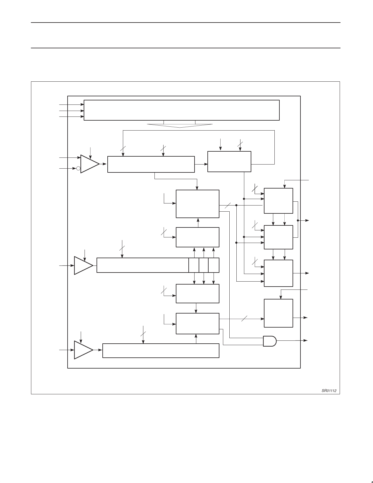
Figure 4. Synthesizer Block Diagram
SR01112
Serial Programming Input
The serial input is a 3-wire input (CLOCK, DATA, STROBE) used to
program all counter ratios, DACs, selection and enable bits. The
programming data is structured into 24-bit words; each word
includes 2 or 3 address bits. Figure [5] shows the timing diagram of
the serial input. When STROBE = L, the clock driver is enabled and
on positive edges of the CLOCK, the signal on DATA input is
clocked into a shift register. When STROBE = H, the clock is
disabled and the data in the shift register remains stable.
Depending on the 2 or 3 address bits, data is latched into different
working or temporary registers. In order to fully program the
synthesizer, 3 words must be sent: A, B and C. The D word
programs all other functions within the SA9024. Those functions are
1997 Aug 01
10
Share Link: 