SA58631 Ver la hoja de datos (PDF) - Philips Electronics
Número de pieza
componentes Descripción
Fabricante
SA58631 Datasheet PDF : 19 Pages
| |||
Philips Semiconductors
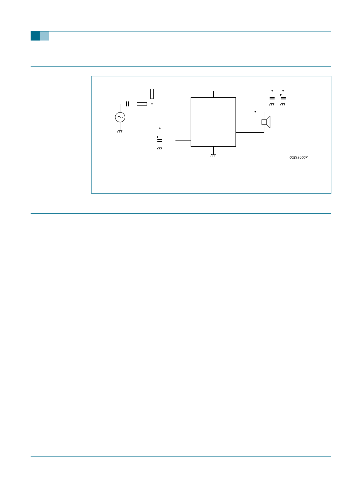
13. Application information
SA58631
3 W BTL audio amplifier
C1
1 µF
R1
11 kΩ
VI
R2
56 kΩ
IN− 4
IN+ 3
SVR 2
C2
47 µF
MODE
1
6
SA58631
100 nF
OUT−
5
RL
8 OUT+
7
GND
VCC
100 µF
002aac007
Gain = 2 × R----2--
R1
Fig 3. Application diagram of SA58631 BTL differential output configuration
14. Test information
14.1 Test conditions
The junction to ambient thermal resistance, Rth(j-a) = 27.7 K/W for the HVSON8 package
when the exposed die attach paddle is soldered to 5 square inch area of 1 ounce copper
heat spreader on the demo PCB. The maximum sine wave power dissipation for
Tamb = 25 °C is:
1---5---0-----–----2---5-- = 4.5 W .
27.7
Thus, for Tamb = +85 °C the maximum total power dissipation is:
1---5---0-----–----8---5-- = 2.35 W .
27.7
The power dissipation versus ambient temperature curve (Figure 5) shows the power
derating profiles with ambient temperature for three sizes of heat spreaders. For a more
modest heat spreader using 1.5 square inch area on the top side of the PCB, the
Rth(j-a) is 31.25 K/W. When the package is not soldered to a heat spreader, the Rth(j-a)
increases to 83.3 K/W.
SA58631
Preliminary data sheet
Rev. 01 — 1 December 2005
© Koninklijke Philips Electronics N.V. 2005. All rights reserved.
6 of 19
Share Link: 