S6510P Ver la hoja de datos (PDF) - AUK -> KODENSHI CORP
Número de pieza
componentes Descripción
Fabricante
S6510P Datasheet PDF : 6 Pages
| |||
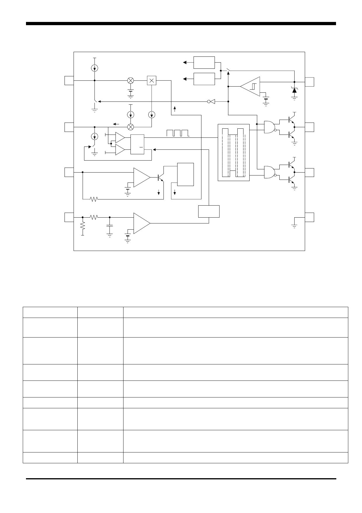
Internal Block Diagram
S6510P
Cs 1
ics
Current Multiplier
-
+
Vref
Ct 2
Rs 3
ic
is
Oscillator
ict
++
-
8ict
SQ
+
-
RQ
+
Buffer
-
+
Vref
2k
ir
2V Vref
Internal
bias
ik = ir / 2
Under Voltage Lock Out
uvlo
+
-
Vth(st)
8 Vcc
18V
Regulator
7 OUT1
Output Driver 1
Current
Mirror
ik
Frequency
Divider
6 OUT2
Output Driver 2
Ldet 4
50 k
10 0k
Vz
10 pF
Vref
No Lamp Detector
-
Delay
Timer
+
Shut Down Signal to OSC
ir = Vref / Rs
ik = ir / 2
is = ik x ( Vref - Vcs) / Vref
5 GND
PIN Collection
Pin Number
1
2
3
4
5
6
7
8
Pin Name
Cs
CT
Rs
Ldet
GND
OUT2
OUT1
Vcc
Pin Function Description
Soft start time capacitor connection pin. The pin charge time to Vref determines
The preheating time of lamp.
Timing capacitor connection pin. The timing capacitor is charged and discharged
To generate the sawtooth waveform that determines the oscillator frequency in
the internal oscillator.
Soft start resistor connection pin. The soft start resistor value determines the
initial soft start frequency for preheating.
Input to the protection circuit. If the pin voltage is lower than Vref, the output oh
The output driver1,2 is inhibited.
Ground of the control Section.
Gate drive output. A push pull output stage is able to drive the Power MOSFET
With peak current of 400mA.
Gate drive output. A push pull output stage is able to drive the Power MOSFET
With peak current of 400mA.
Supply Voltage of output driver and control circuits.
KSI-L014-000
2
Share Link: 