RT9204 Ver la hoja de datos (PDF) - Richtek Technology
Número de pieza
componentes Descripción
Fabricante
RT9204 Datasheet PDF : 14 Pages
| |||
Preliminary
RT9204/A
Application Information
The RT9204/A operates at either single 5V power supply
with a bootstrap UGATE driver or 5V/12V dual-power
supply form the ATX SMPS. The dual- power supply is VCC
recommended for high current application, the
RT9204/A can deliver higher gate driving current while
operating with ATX SMPS based on dual-power supply.
The Bootstrap Operation
6.0V
Regulation
C2
RT9204/A
1uF
BOOT
UGATE
R
C 10
1uF
12V
5V
In a single power supply system, the UGATE driver of
RT9204/A is powered by an external bootstrap circuit, as
the Figure 3. The boot capacitor, CBOOT, generates a
floating reference at the PHASE node. Typically a 0.1µF
CBOOT is enough for most of MOSFETs used with the
RT9204/A. The voltage drop between BOOT and PHASE
node is refreshed to a voltage of VCC−diode drop (VD)
while the low side MOSFET turning on.
R1
VCC
BOOT
D1
5V
C2
1uF
UGATE
0.1uF
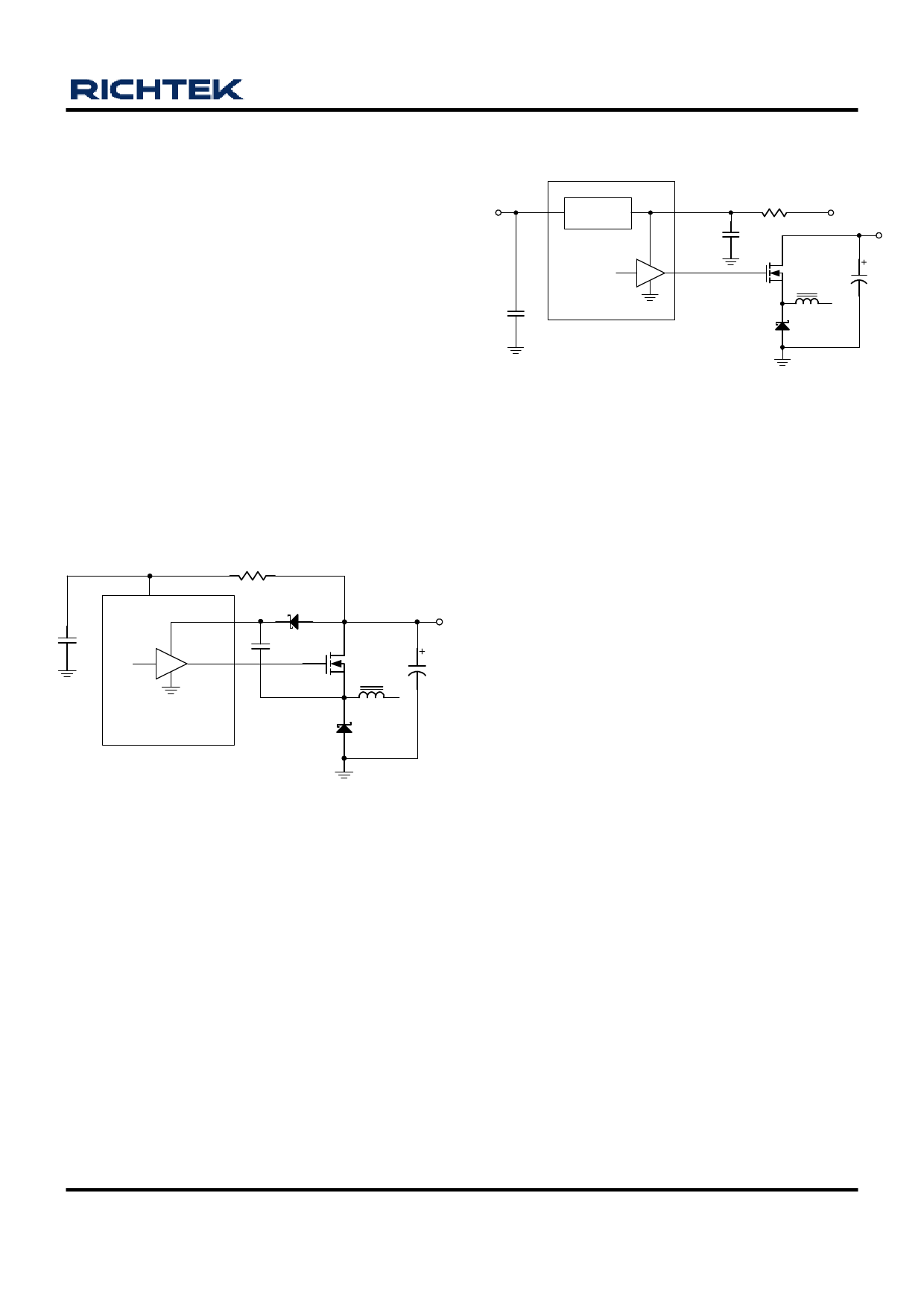
Figure 4. Dual Power Supply Operation
Power On Reset
The Power-On Reset (POR) monitors the supply voltage
(normal +5V) at the VCC pin and the input voltage at the
OCSET pin. The VCC POR level is 4.1V with 0.5V
hysteresis and the normal level at OCSET pin is 1.5V
(see over-current protection). The POR function initiates
soft-start operation after all supply voltages exceed their
POR thresholds.
Soft Start
RT9204/A
PHASE
Figure 3. Single 5V power Supply Operation
A built-in soft-start is used to prevent surge current from
power supply input during power on. The soft-start voltage
is controlled by an internal digital counter. It clamps the
ramping of reference voltage at the input of error amplifier
and the pulse-width of the output driver slowly. The typical
soft-start duration is 2ms.
Under Voltage and Over Voltage Protection
Dual Power Operation
The RT9204/A was designed to regulate a 6.0V at VCC
pin automatically when BOOT pin is powered by 12V. In
a system with ATX 5V/12V power supply, the RT9204 is
ideal for higher current application due to the higher gate
driving capability, VUGATE = 7V. A RC (10Ω/1µF) filter is
also recommended at BOOT pin to prevent the ringing
induced from fast power on, as shown in Figure 4.
The voltage at FB pin is monitored and protected against
OC (over current), UV (under voltage), and OV (over
voltage). The UV threshold is 0.5V and OV-threshold is
1.0V. Both UV/OV detection have 30µs triggered delay.
When OC or UV trigged, a hiccup re-start sequence will
be initialized, as shown in Figure 5. For RT9204, only 3
times of trigger are allowed to latch off. But for RT9204A,
UVP will be kept hiccup mode. Hiccup is disabled during
soft-start interval.
DS9204/A-08 March 2007
www.richtek.com
9
Share Link: 