RT9202B Ver la hoja de datos (PDF) - Richtek Technology
Número de pieza
componentes Descripción
Fabricante
RT9202B Datasheet PDF : 14 Pages
| |||
RT9202B
Both VSET and VDS are referenced to VIN and a small
capacitor across ROCSET helps VOCSET tracking the
variations of VIN due to MOSFET switching. The over-
current function will be tripped at a peak inductor current
(IPEAK) determined by :
IPEAK
= IOCSET × ROCSET
RDS(ON)
The OC trip point varies with MOSFET's RDS(ON)
temperature variations. The temperature coefficient of
IOCSET is 2500ppm that is used to compensate RDS(ON)
temperature variations. To avoid over-current tripping in
the normal operating load range, determine the ROCSET
resistor value from the equation above with:
1.The maximum RSD(ON) at the highest junction
temperature
2.The minimum IOCSET from the characteristics
3.Determine IPEAK for IPEAK > IOUT(MAX) + (∆I)/2
where ∆I is the output inductor ripple current.
OVER-CURRENT TRIP:
VDS > VSET
iD × RDS(ON) > IOCSET × ROCSET
OCSET
IOCSET
20uF
DRIVE
ROCSET
VSET+
VCC
UGATE
VIN = +5V
iD
VDS+
+
-
OC
PWM
GATE
CONTROL
PHASE
VPHASE = VIN - VDS
VOCSET = VIN - VSET
Figure 3
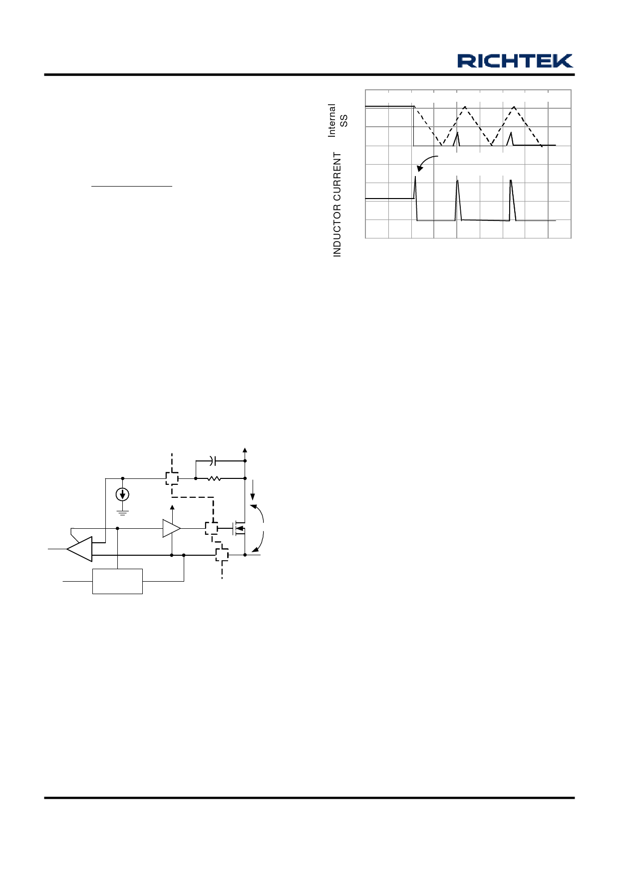
Under Voltage and Over Voltage Protection
The voltage at FB pin is monitored and protected against
OC (over current), UV (under voltage), and OV (over
voltage). The UV threshold is 0.5V and OV-threshold is
1.0V. Both UV/OV detection have 30µs triggered delay.
When OC or UV trigged, a hiccup re-start sequence will
be initialized, as shown in Figure 4. Only 3 times of trigger
are allowed to latch off. Hiccup is disabled during soft-
start interval.
COUNT = 1 COUNT = 2 COUNT = 3
4V
2V
0V
OVERLOAD
APPLIED
0A
T0 T1
T2
T3
TIME
Figure 4
Shutdown
Pulling low the OCSET pin can shutdown the RT9202B
PWM controller as shown in typical application circuit.
Inductor Selection
The RT9202B was designed for VIN = 5V, step-down
application mainly. Figure 5 shows the typical topology
and waveforms of step-down converter.
The ripple current of inductor can be calculated as follows:
ILRIPPLE = (5V - VOUT)/L × TON
Because operation frequency is fixed at 300kHz,
TON = 3.33 × VOUT/5V
The VOUT ripple is
VOUT RIPPLE = ILRIPPLE × ESR
ESR is output capacitor equivalent series resistor
Table 1 shows the ripple voltage of VOUT : VIN = 5V
www.richtek.com
10
DS9202B-03 March 2007
Share Link: 