RT9164A Ver la hoja de datos (PDF) - Richtek Technology
Número de pieza
componentes Descripción
Fabricante
RT9164A Datasheet PDF : 14 Pages
| |||
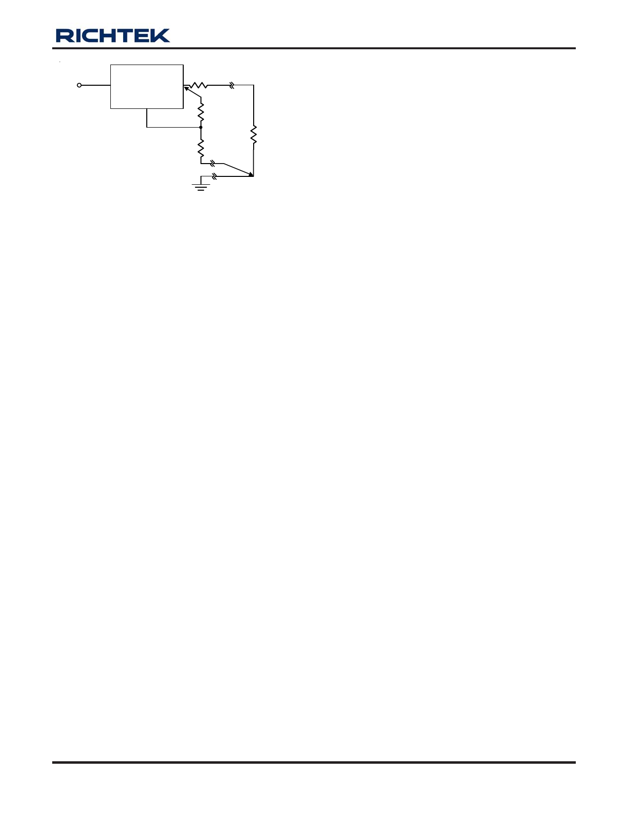
RT9164A
RP Parasitic
Line Resistance
VIN
VIN
VOUT
ADJ
R1
(Connect R1 to VOUT
or case)
R2
RL
Connect R2 to load
Figure 6. Best Load Regulation Using Adjustable
Output Regulator
Thermal Protection
RT9164A has thermal protection which limits junction
temperature to 150°C. However, device functionality is only
guaranteed to a maximum junction temperature of +125°C.
The power dissipation and junction temperature for RT9164A
are given by
PD = (VIN - VOUT) x IOUT
TJUNCTION = TAMBIENT + (PD x θJA)
Note: TJUNCTION must not exceed 125°C
Current Limit Protection
RT9164A is protected against overload conditions. Current
protection is triggered at typically 1.8A.
Thermal Consideration
The RT9164A series contain thermal limiting circuitry
designed to protect itself from over-temperature conditions.
Even for normal load conditions, maximum junction
temperature ratings must not be exceeded. As mention in
thermal protection section, we need to consider all sources
of thermal resistance between junction and ambient. It
includes junction-to-case, case-to-heat-sink interface, and
heat sink thermal resistance itself.
Junction-to-case thermal resistance is specified from the
IC junction to the bottom of the case directly below the
die. Proper mounting is required to ensure the best possible
thermal flow from this area of the package to the heat
sink. The case of all devices in this series is electrically
connected to the output. Therefore, if the case of the device
must be electrically isolated, a thermally conductive spacer
is recommended.
DS9164A-13 August 2007
RT9164A
www.richtek.com
11
Share Link: 