RT8272 Ver la hoja de datos (PDF) - Richtek Technology
Número de pieza
componentes Descripción
Fabricante
RT8272 Datasheet PDF : 12 Pages
| |||
RT8272
Application Information
The RT8272 is an asynchronous high voltage buck
converter that can support the input voltage range from
4.75V to 24V and the output current can be up to 3A.
Output Voltage Setting
The resistive divider allows the FB pin to sense the output
voltage as shown in Figure 1.
VOUT
R1
FB
RT8272
R2
GND
Figure 1. Output Voltage Setting
The output voltage is set by an external resistive divider
according to the following equation :
VOUT
=
VFB
⎛⎜⎝1+
R1
R2
⎞⎟⎠
Where VFB is the feedback reference voltage (0.92V typ.).
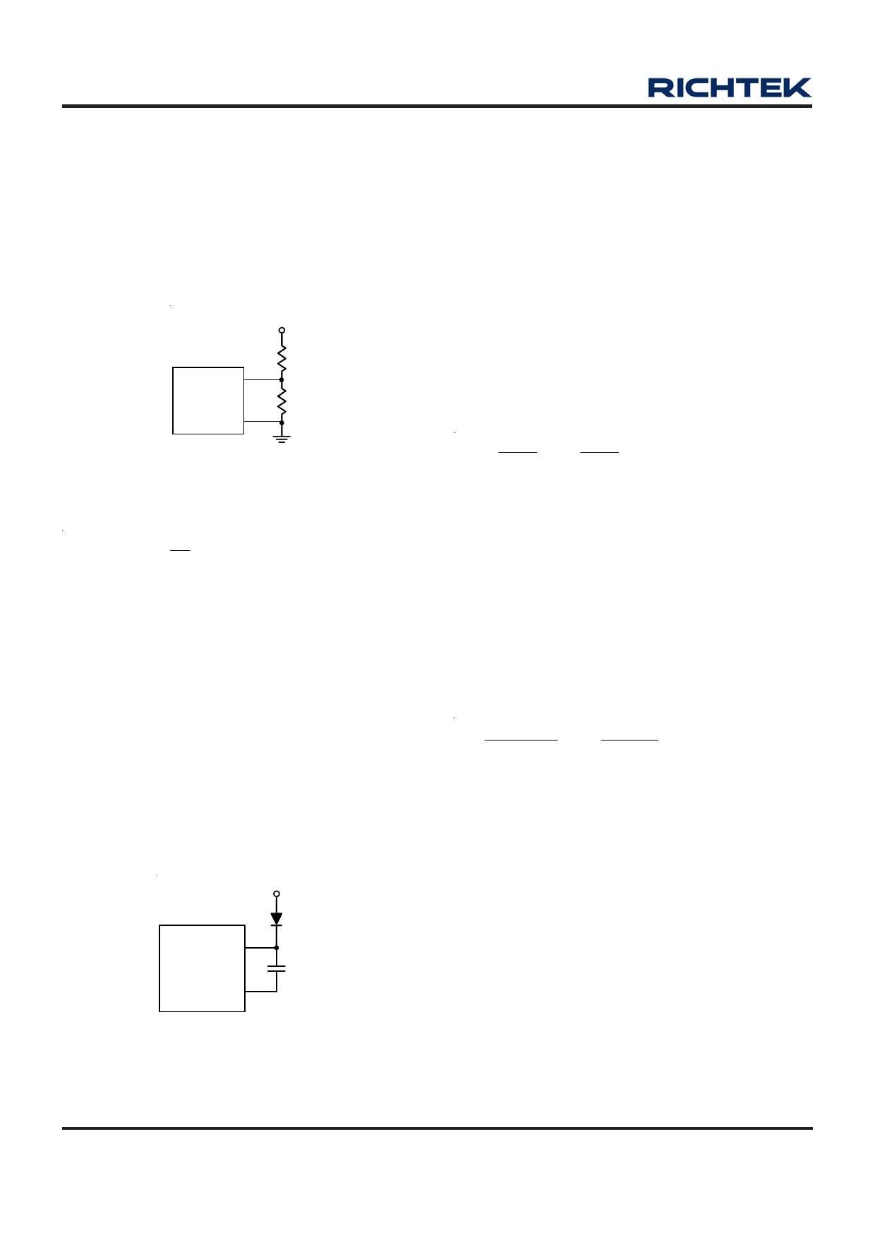
External Bootstrap Diode
Connect a 10nF low ESR ceramic capacitor between the
BOOT pin and SW pin. This capacitor provides the gate
driver voltage for the high side MOSFET.
It is recommended to add an external bootstrap diode
between an external 5V and the BOOT pin for efficiency
improvement when input voltage is lower than 5.5V or duty
ratio is higher than 65%. The bootstrap diode can be a
low cost one such as 1N4148 or BAT54.
The external 5V can be a 5V fixed input from system or a
5V output of the RT8272.
5V
BOOT
RT8272
SW
10nF
Figure 2. External Bootstrap Diode
www.richtek.com
8
Soft-Start
The RT8272 contains an external soft-start clamp that
gradually raises the output voltage. The soft-start timming
can be programed by the external capacitor between SS
pin and GND. The chip provides a 10μA charge current for
the external capacitor. If 0.1μF capacitor is used to set
the soft-start and it’ s period will be 10ms(typ.).
Inductor Selection
The inductor value and operating frequency determine the
ripple current according to a specific input and output
voltage. The ripple current ΔIL increases with higher VIN
and decreases with higher inductance.
ΔIL
=
⎡
⎢⎣
VOUT
f ×L
⎤
⎥⎦
×
⎡⎢⎣1−
VOUT
VIN
⎤
⎥⎦
Having a lower ripple current reduces not only the ESR
losses in the output capacitors but also the output voltage
ripple. High frequency with small ripple current can achieve
highest efficiency operation. However, it requires a large
inductor to achieve this goal.
For the ripple current selection, the value of ΔIL = 0.4(IMAX)
will be a reasonable starting point. The largest ripple
current occurs at the highest VIN. To guarantee that the
ripple current stays below the specified maximum, the
inductor value should be chosen according to the following
equation :
L
=
⎡
⎢⎣
f
×
VOUT
ΔIL(MAX)
⎤
⎥⎦
×
⎡⎢⎣1−
VOUT
VIN(MAX)
⎤
⎥⎦
Inductor Core Selection
The inductor type must be selected once the value for L
is known. Generally speaking, high efficiency converters
can not afford the core loss found in low cost powdered
iron cores. So, the more expensive ferrite or
mollypermalloy cores will be a better choice.
The selected inductance rather than the core size for a
fixed inductor value is the key for actual core loss. As the
inductance increases, core losses decrease. Unfortunately,
increase of the inductance requires more turns of wire
and therefore the copper losses will increase.
Ferrite designs are preferred at high switching frequency
due to the characteristics of very low core losses. So,
design goals can focus on the reduction of copper loss
and the saturation prevention.
DS8272-02 March 2011
Share Link: 