RT8062GSP Ver la hoja de datos (PDF) - Richtek Technology
Número de pieza
componentes Descripción
Fabricante
RT8062GSP Datasheet PDF : 11 Pages
| |||
RT8062
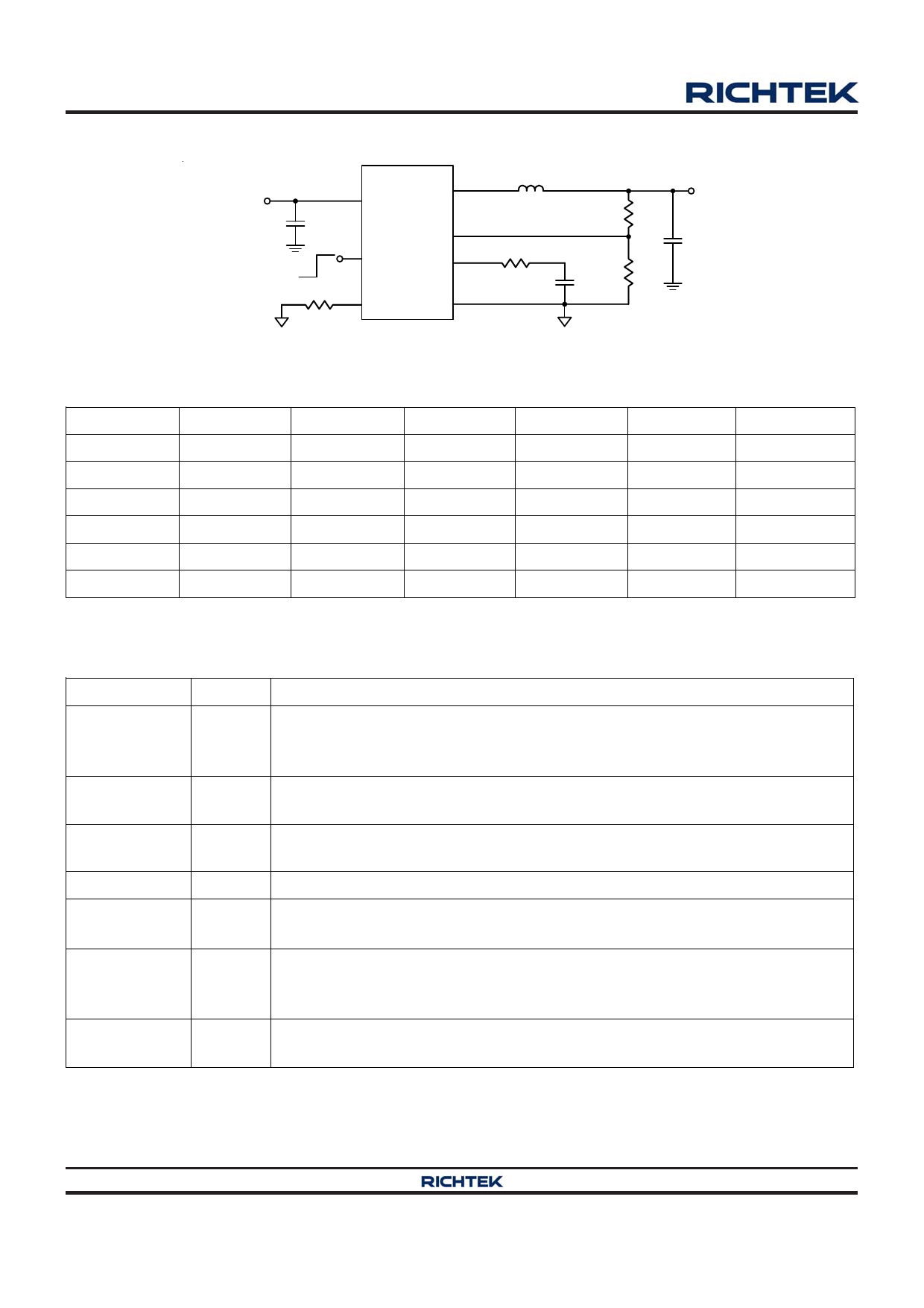
Typical Application Circuit
VIN
2.7V to 5.5V
CIN
10µF
4
RT8062
VIN
LX
5, 6
3 EN
FB 8
COMP 1
L
RCOMP
ROSC 7 RT
GND 2,
9 (Exposed Pad)
R1
R2
CCOMP
VOUT
COUT
Note : Using all Ceramic Capacitors
VOUT (V)
3.3
2.5
1.8
1.5
1.2
1.0
Table 1. Recommended Components Selection for fSW = 1MHz
R1 (kΩ)
R2 (kΩ)
RCOMP (kΩ) CCOMP (pF)
L (μH)
75
24
33
560
2.0
51
24
22
560
2.0
30
24
15
560
1.5
21
24
13
560
1.5
12
24
11
560
1.5
6
24
8.2
560
1.5
COUT (μF)
22
22
22
22
22
22
Functional Pin Description
Pin No.
Pin Name
Pin Function
Error Amplifier Compensation Point. The current comparator threshold increases
1
COMP with this control voltage. Connect external compensation elements to this pin to
stabilize the control loop.
2,
GND
9 (Exposed Pad)
Ground. The exposed pad must be soldered to a large PCB and connected to GND
for maximum power dissipation.
Enable Control Input. Float or connect this pin to logic high for enable. Connect to
3
EN
GND for disable.
4
VIN
Power Input Supply. Decouple this pin to GND with a capacitor.
5, 6
LX
7
RT
8
FB
Internal Power MOSFET Switches Output. Connect these pins to the inductor
together.
Oscillator Resistor Input. Connecting a resistor from this pin to GND sets the
switching frequency. If this pin is floating, the frequency will be set at 2MHz
internally.
Feedback. Receives the feedback voltage from a resistive divider connected across
the output.
Copyright ©2012 Richtek Technology Corporation. All rights reserved.
www.richtek.com
2
is a registered trademark of Richtek Technology Corporation.
DS8062-07 November 2012
Share Link: 